Computer Systems Experiments 5 | Power an LED with GPIO
Computer Systems Experiments 5 | Power an LED with GPIO
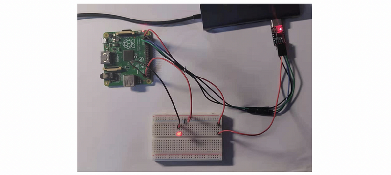
In Experiment 2, we have lightened an LED by the 5V power pin on the Raspberry Pi. Now, we would like to power an LED light with the GPIO pin. In this case, we choose GPIO21 only because it is at the right-down corner of the Pi without any other purposes. Note that you can also choose some other GPIOs and we will see that in an example.
To continue, we have to learn some assembly language in order to meet the minimum expectation of this experiment. We have to know three basic mnemonics LDR, STR, and MOV.
MOVis the simplest mnemonic that is used for moving register or constant. For example,
MOV r1, #1
means to move an immediate value 1 to the register r1.
LDRis the mnemonic used to load data to register from the memory. For example, when r0 contains an address of the data we want to load, we would like to load the data at address r0 to r1,
LDR r1, [r0]
STRmeans to set the data to the memory. For example, when r0 contains an address of the data we want to load, we would like to set the data at r1 to the address r0,
STR r1, [r0]
Also, we have to know that label: .word value places the 4-byte value at the address assigned (by the linker) to label. For example,
FSEL0: .word 0x20200000
Okay, now we are fine to move on. Let’s now refer to the instruction of BCM2835 on page 90.
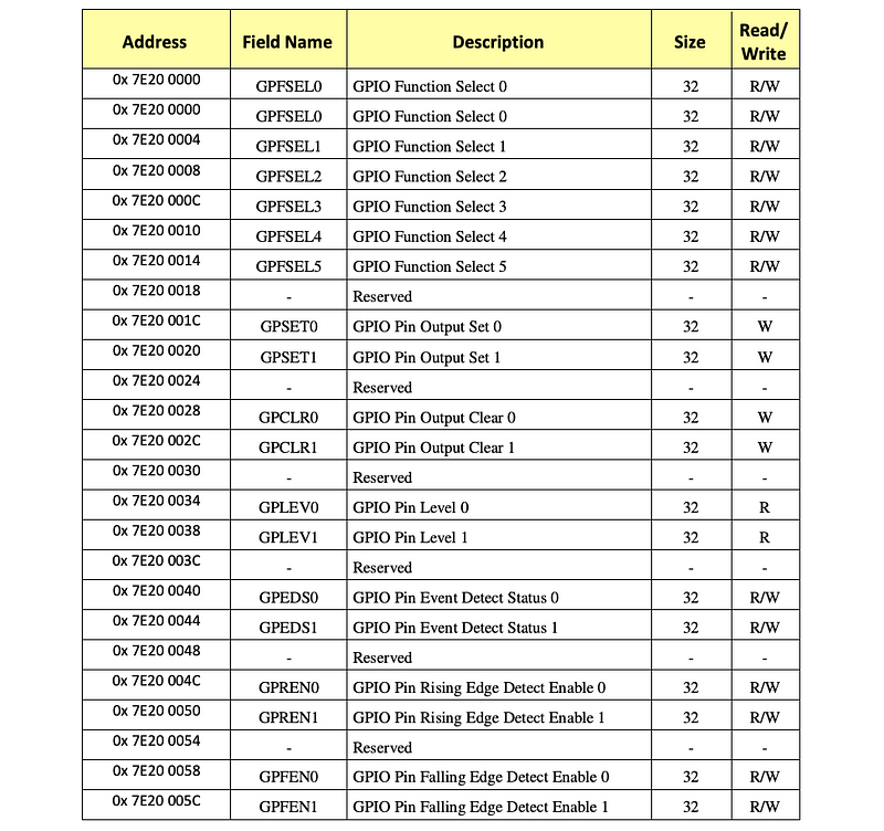
Note that we have mentioned in the preparation part that the address in the manual 0x7E... is the logical address and we will change it 0x20... in the code.
- Set the GPIO 21 pin to output
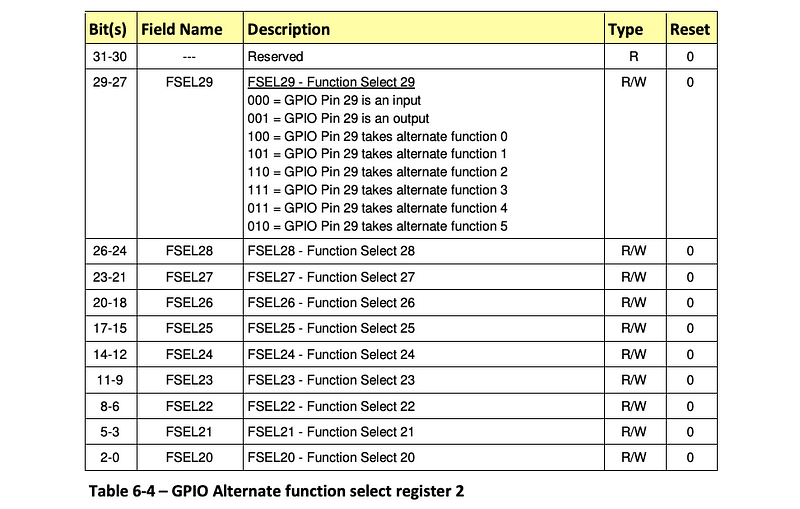
First, let’s change the GPIO 21 pin to output. According to the instructions, we should change the value on the address GPFSEL2 from,
0000 0000 0000 0000 0000 0000 0000 0000
to,
0000 0000 0000 0000 0000 0000 0000 1000
so the 5–3 bits are then 001 and this means the GPIO21 is an output. The assembly for this is,
// configure GPIO 21 for output
ldr r0, GPFSEL2
mov r1, #8
str r1, [r0]
The reason why we use the immediate value 8 is that the decimal number 8 equals the binary number 1000.
2. Set the GPIO 21 pin high
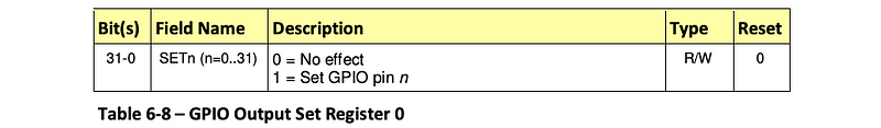
Secondly, let’s change the GPIO 21 pin high. According to the instructions, we should change the value on the address SET0 from,
0000 0000 0000 0000 0000 0000 0000 0000
to,
0000 0000 0010 0000 0000 0000 0000 0000
this can be easily done by the bitwise left shifting,
1<<21
and the assembly for this is,
// set GPIO 21 high
ldr r0, SET0
str r1, [r0]
3. Give the labels
Remember to set the labels of our code,
GPFSEL2: .word 0x20200008
SET0:  .word 0x2020001C
So, in general, our code should finally be,
// configure GPIO 21 for output
ldr r0, GPFSEL2
mov r1, #8
str r1, [r0]
mov r1, #(1<<21)
// set GPIO 21 high
ldr r0, SET0
str r1, [r0]
GPFSEL2: .word 0x20200008
SET0:  .word 0x2020001C
I named it as GPIOled.s .
4. Assemble GPIOled.s
Finally, we have to make our code easy to read for the Pi, which means we have to assemble it in the machine language (to .bin files). We can write a Makefile file but now we would like to try this manually,
$ arm-none-eabi-as GPIOled.s -o GPIOled.o
$ arm-none-eabi-objcopy GPIOled.o -O binary GPIOled.bin
$ rpi-install.py GPIOled.bin
You can find my files from the folder GPIO led. If there’s nothing wrong, we can now power our LED with the GPIO21 pin.
Exercise. This is used to test whether you have understood all the stuff above. Now, suppose we would like to use the GPIO16 pin to power our LED, what should be the content in our assembly file exercise.s?
Hint: Here is the code to assemble our code
$ arm-none-eabi-as exercise.s -o exercise.o
$ arm-none-eabi-objcopy exercise.o -O binary exercise.bin
$ rpi-install.py exercise.bin
Answer:
ldr r0, GPFSEL1
mov r1, #(1<<18)
str r1, [r0]
mov r1, #(1<<16)
ldr r0, SET0
str r1, [r0]
GPFSEL1: .word 0x20200004
SET0: .word 0x2020001c