Computer Systems Experiments 6 | Blinking LED
Computer Systems Experiments 6 | Blinking LED

We have learned how to power an LED with the GPIO pins, now let’s try to make the LED blinking. The method that we can make it blinking is by looping and delay. To continue our discussion, we have to know more about the assembly language.
.equmeans to assign a constant variable. For example,
.equ DELAY, 0x3F0000means to assign0x3F0000 to DELAY. To use this variable as an immediate value, we have to add a # in front of the DELAY like #DELAY .
- Infinite Loop: Basically, we use the
bmnemonic to create an infinite loop,
loop:
b loop
- Delay Structure: We usually use certain times of subtracting calculations to delay a status. The difference between
subandsubsis that the latter one will change the flag after the subtraction. Thebnemeans that if the result is not 0 then branch to the wait.
mov r2, #DELAY
wait:
    subs r2, r2, #1
    bne wait
This code means to reduce the value in r2 by 1 at a time until it equals 0.
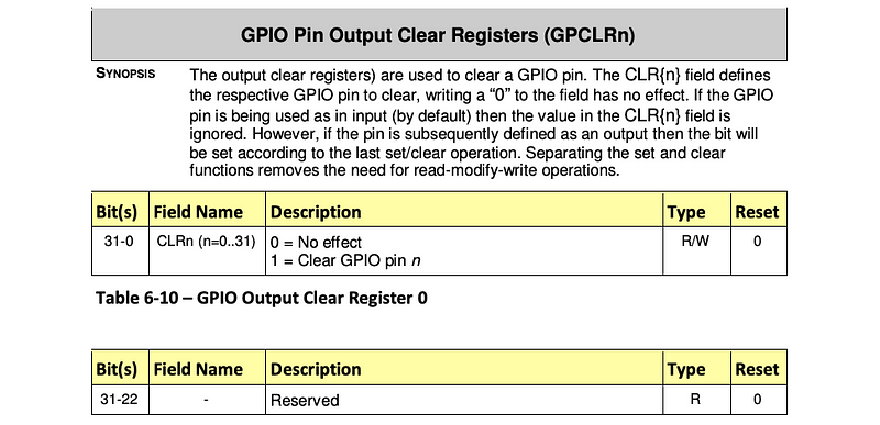
Okay, now, let’s move on to our blinking LED. Let’s now refer to the instruction of BCM2835 on page 95 about the CLR. This is a register that we can clear the high status of a specific pin.
We are going to continue with our code from the last experiment with GPIO21,
// configure GPIO 21 for output
ldr r0, GPFSEL2
mov r1, #8
str r1, [r0]
mov r1, #(1<<21)
// set GPIO 21 high
ldr r0, SET0
str r1, [r0]
GPFSEL2: .word 0x20200008
SET0: .word 0x2020001C
- Add the delay time
.equ DELAY, 0x3F0000// configure GPIO 21 for output
ldr r0, GPFSEL2
mov r1, #8
str r1, [r0]
mov r1, #(1<<21)
// set GPIO 21 high
ldr r0, SET0
str r1, [r0]
// delay a certain time
wait:
subs r2, r2, #DELAY
bne wait
GPFSEL2: .word 0x20200008
SET0: .word 0x2020001C
2. Add the CLR register
.equ DELAY, 0x3F0000// configure GPIO 21 for output
ldr r0, GPFSEL2
mov r1, #8
str r1, [r0]
mov r1, #(1<<21)
// set GPIO 21 high
ldr r0, SET0
str r1, [r0]
// delay a certain time
mov r2, #DELAY
wait1:
subs r2, r2, #1
bne wait1
// clear GPIO 21 status
ldr r0, CLR0
str r1, [r0]
// delay a certain time
mov r2, #DELAY
wait2:
subs r2, r2, #1
bne wait2
GPFSEL2: .word 0x20200008
SET0: .word 0x2020001C
CLR0: .word 0x20200028
Notice that if we assemble this code, the LED will blink just one time. Actually, we want it to blink infinitely and that’s why we have to add an infinite loop to the code.
3. Add Infinite Loop
.equ DELAY, 0x3F0000
// configure GPIO 21 for output
ldr r0, GPFSEL2
mov r1, #8
str r1, [r0]
mov r1, #(1<<21)
loop:
// set GPIO 21 high
ldr r0, SET0
str r1, [r0]
// delay a certain time
mov r2, #DELAY
wait1:
subs r2, r2, #1
bne wait1
// clear GPIO 21 status
ldr r0, CLR0
str r1, [r0]
// delay a certain time
mov r2, #DELAY
wait2:
subs r2, r2, #1
bne wait2
b loop
GPFSEL2: .word 0x20200008
SET0: .word 0x2020001C
CLR0: .word 0x20200028
Then we can assemble this code by,
$ arm-none-eabi-as blink.s -o blink.o
$ arm-none-eabi-objcopy blink.o -O binary blink.bin
$ rpi-install.py blink.bin
Hooray! Our LED is blinking now!