Computer Systems Experiments 7 | Button Controlled Blinking LED and Pull-up Resistor
Computer Systems Experiments 7 | Button Controlled Blinking LED and Pull-up Resistor

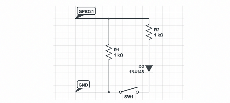
This task can be easy to some extent because we can directly add a button in the circuit and also a parallel resistor to avoid the open circuit.
However, we would like to try something new because we want to try the GPIO input. In this case, we are going to use the GPIO10 for the input signal because GPIO10 is from GPFSEL1 and we only have to change the last bit (actually we don’t have to change it because the last bit is zero by default).
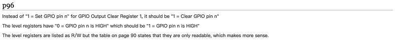
According to the instructions of BCM2835 and the errata,
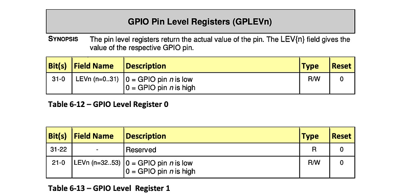
It can be aware that the LEV0 registers can be used to read the status of a specific pin. Now, let’s code the assembly file for our purpose. Our purpose is that when we press the button, the LED will be set to on and it will be blinking. When we release the button, the LED will be set to off. We will continue with our blink.s file.
.equ DELAY, 0x3F0000
// configure GPIO 21 for output
ldr r0, FSEL2
mov r1, #8
str r1, [r0]
mov r1, #(1<<21)
loop:
// set GPIO 21 high
 ldr r0, SET0
 str r1, [r0]
// delay a certain time
 mov r2, #DELAY
 wait1:
     subs r2, r2, #1
     bne wait1
// clear GPIO 21 status
 ldr r0, CLR0
 str r1, [r0]
// delay a certain time
 mov r2, #DELAY
 wait2:
     subs r2, r2, #1
     bne wait2

b loop
FSEL1: .word 0x20200004
FSEL2: .word 0x20200008
SET0: .word 0x2020001C
CLR0: .word 0x20200028
- Configure GPIO 10 for input
.equ DELAY, 0x3F0000
// configure GPIO 10 for input
ldr r0, FSEL1
mov r1, #0
str r1, [r0]
// configure GPIO 21 for output
ldr r0, FSEL2
mov r1, #8
str r1, [r0]
mov r1, #(1<<21)
loop:
// set GPIO 21 high
 ldr r0, SET0
 str r1, [r0]
// delay a certain time
 mov r2, #DELAY
 wait1:
     subs r2, r2, #1
     bne wait1
// clear GPIO 21 status
 ldr r0, CLR0
 str r1, [r0]
// delay a certain time
 mov r2, #DELAY
 wait2:
     subs r2, r2, #1
     bne wait2

b loop
FSEL1: .word 0x20200004
FSEL2: .word 0x20200008
SET0: .word 0x2020001C
CLR0: .word 0x20200028
2. Assign bit 10 and bit 21 to r2 and r3
.equ DELAY, 0x3F0000
// configure GPIO 10 for input
ldr r0, FSEL1
mov r1, #0
str r1, [r0]
// configure GPIO 21 for output
ldr r0, FSEL2
mov r1, #8
str r1, [r0]
// bit 10 and bit 21
mov r2, #(1<<10)
mov r3, #(1<<21)
loop:
// set GPIO 21 high
 ldr r0, SET0
 str r1, [r0]
// delay a certain time
 mov r2, #DELAY
 wait1:
     subs r2, r2, #1
     bne wait1
// clear GPIO 21 status
 ldr r0, CLR0
 str r1, [r0]
// delay a certain time
 mov r2, #DELAY
 wait2:
     subs r2, r2, #1
     bne wait2

b loop
FSEL1: .word 0x20200004
FSEL2: .word 0x20200008
SET0: .word 0x2020001C
CLR0: .word 0x20200028
3. Add reading GPIO10 at the beginning of every loop
Note that we have used tst in this part and tst r1, r2 computes the bitwise AND of r1 and r2 and then discards the result while cmp r1, r2 subtracts the two. For example, when
r1 = 0110
r2 = 0010
The AND result of r1 and r2 is,
0010
We are going to use tst in our case,
.equ DELAY, 0x3F0000
// configure GPIO 10 for input
ldr r0, FSEL1
mov r1, #0
str r1, [r0]
// configure GPIO 21 for output
ldr r0, FSEL2
mov r1, #8
str r1, [r0]
// bit 10 and bit 21
mov r2, #(1<<10)
mov r3, #(1<<21)
loop:
 // read GPIO10
 ldr r0, LEV0
 ldr r1, [r0]
 tst r1, r2
 beq on // when the button is pressed (goes LOW), turn on LED
 // set GPIO 21 high
 ldr r0, SET0
 str r1, [r0]
 // delay a certain time
 mov r2, #DELAY
 wait1:
     subs r2, r2, #1
     bne wait1
 // clear GPIO 21 status
 ldr r0, CLR0
 str r1, [r0]
 // delay a certain time
 mov r2, #DELAY
 wait2:
     subs r2, r2, #1
     bne wait2

b loop
FSEL1: .word 0x20200004
FSEL2: .word 0x20200008
SET0: .word 0x2020001C
CLR0: .word 0x20200028
LEV0:  .word 0x20200034
4. Differ on and off status
.equ DELAY, 0x3F0000
// configure GPIO 10 for input
ldr r0, FSEL1
mov r1, #0
str r1, [r0]
// configure GPIO 21 for output
ldr r0, FSEL2
mov r1, #8
str r1, [r0]
// bit 10 and 21
mov r2, #(1<<10)
mov r3, #(1<<21)
loop:
    // read GPIO 10
    ldr r0, LEV0
    ldr r1, [r0]
    tst r1, r2
    beq on // when the button is pressed (goes LOW), turn on LED

    off:
        ldr r0, CLR0
        str r3, [r0]
        b loop
    on:
        // set GPIO 21 high
        ldr r0, SET0
        str r3, [r0]
        // delay a certain time
        mov r4, #DELAY
        wait1:
            subs r4, r4, #1
            bne wait1
        // clear GPIO 21 status
        ldr r0, CLR0
        str r3, [r0]
        // delay a certain time
        mov r4, #DELAY
        wait2:
            subs r4, r4, #1
            bne wait2
b loop
FSEL1: .word 0x20200004
FSEL2: .word 0x20200008
SET0: .word 0x2020001C
CLR0: .word 0x20200028
LEV0:  .word 0x20200034
5. The design of the pull-up resistor
A pull-up resistor connects unused input pins to the dc supply voltage to keep the given input HIGH. When the button is pressed, the given input will then be LOW. We have to add this resistor because we don’t want a short circuit when the button is pushed. That’s why we must add this resistor.
A similar concept is a pull-down resistor which connects unused input pins to the dc supply voltage to keep the given input LOW. When the button is pressed, the given input will then be HIGH. Actually, the pull-up resistor is more commonly used than the pull-down resistor, so we are going to use the pull-up resistor in this case.
In our case, when the button is pressed, the GPIO 10 pin will be connected to GND and thus the input of this pin will be given as LOW. Instead, when the button is not released, then the GPIO 10 pin will be connected to the 5V power and the input of this pin will be given as HIGH.
In our code, when the GPIO 10 pin is given HIGH (no pressed button), the result of tst r1, r2 is not equal because
r1 = 0000 0000 0000 0000 0000 0100 0000 0000
r2 = 0000 0000 0000 0000 0000 0000 0000 0000
And the result of tst is (AND calculation),
0000 0000 0000 0000 0000 0000 0000 0000
That means the Z flag is zero.
when the GPIO 10 pin is given LOW (with pressed button), the result of tst r1, r2 is equal because
r1 = 0000 0000 0000 0000 0000 0100 0000 0000
r2 = 0000 0000 0000 0000 0000 0100 0000 0000
And the result of tst is (AND calculation),
0000 0000 0000 0000 0000 0100 0000 0000
That means the Z flag is not zero.
The circuit of this experiment is,
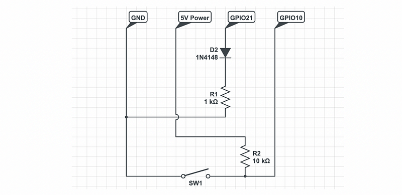
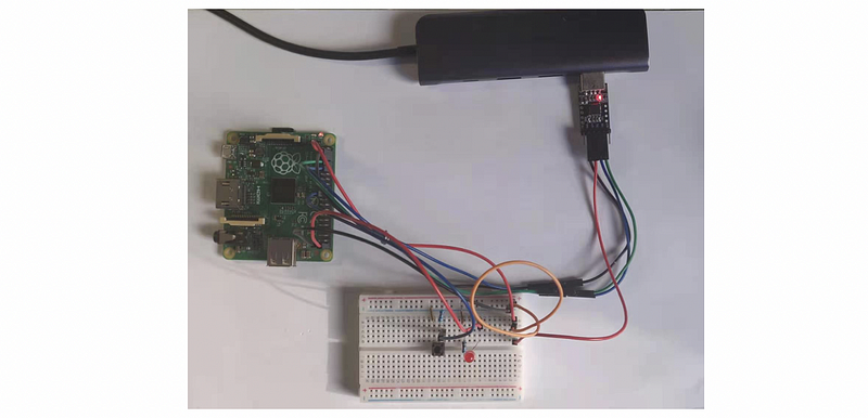
and you can find the code from my repo.
Common mistakes:
- The 10k resistor should be connected to the 5V power pin. Don’t connect it with the GPIO 21 pin.
- The pull-up resistor should be connected between the 5C power pin and the GPIO 10 pin.
- The control button (switch) should be connected between the GND and the 10k pull-up resistor.