Computer Systems Experiments 8 | Larson Scanner
Computer Systems Experiments 8 | Larson Scanner

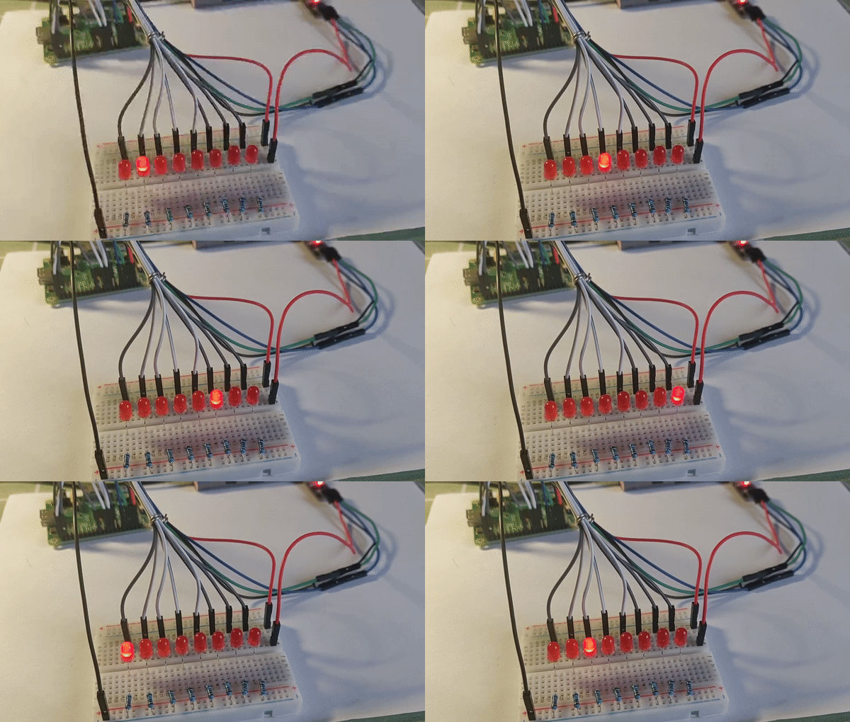
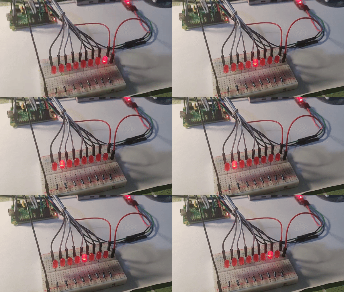
In this experiment, we are going to create a Larson Scanner. The Larson scanner is named after Glen A. Larson, the man responsible for producing both the original Battlestar Galactica and Knight Rider television shows. You can find a video that shows the demo of a Larson Scanner on the left-hand side of this paragraph.
The leftmost LED in your scanner should be connected to GPIO 20 of your Raspberry Pi, the second from the left to GPIO 21, and so on, such that the rightmost LED in your scanner is connected to GPIO 27 for using 8 LEDs.
- Set the output functions to GPIO 20 to 27
To set the input function of the GPIO 20 to 27 we should set the value of FSEL2 to,
0000 0000 0010 0100 1001 0010 0100 1001
This value equal to the hexadecimal number,
0x249249
If we directly assign this value to a register, there will be an error,
// set output to GPIO 20 to 27, false code
ldr r0, FSEL2
mov r1, #0x249249
ldr r1, [r0]
This is because we can load it or build up the register 8 non-zero bits at a time. We can use ldr to assign this value,
// set output to GPIO 20 to 27
ldr r0, FSEL2
ldr r1, =0x00249249
ldr r1, [r0]
2. Set the starting status
// set the starting status
mov r2, #(1<<20) // current pin
3. Create a one-way scanner
We actually want the feature that the light goes from one side (left) to the other side (right), and then it will come back from the right side to the left. However, let’s do it step by step. How about we first create a one-way scanner that only goes from the left side to the right side? That’s easier.
restart:
 // set the starting status
 mov r1, #(1<<20) // current pin
loop:
   ldr r0, SET0
   str r1, [r0]
   // delay a certain time
   mov r2, #DELAY
   wait1:
       subs r2, r2, #1
       bne wait1
   // clear GPIO status
   ldr r0, CLR0
   str r1, [r0]

   lsl r1, #1
   tst r1, #(1<<29)
   beq loop
   bne restart

4. Develop a two-way scanner
The difference between the one-way scanner and the two-way scanner is that we have to add a conditional structure and tell when the light should move from the left to the right and when the light should move the opposite way. In this case, we are going to hard code the values (i.e. 19, 21, 26, 28) and we are going to make it a more general case in the next experiment.
The full code for the Larson Scanner is,
.equ DELAY, 0x3F0000
// set output to GPIO 20 to 27
ldr r0, FSEL2
ldr r1, =0x00249249
str r1, [r0]
// set the starting status
mov r1, #(1<<20) // current pin
mov r3, #1 //start with forward
loop:
  ldr r0, SET0
  str r1, [r0]
  // delay a certain time
  mov r2, #DELAY
  wait1:
      subs r2, r2, #1
      bne wait1
  // clear GPIO status
  ldr r0, CLR0
  str r1, [r0]
  tst r3, #1
  bne forward
  beq backward

forward:
  lsl r1, #1
  b compar
backward:
  lsr r1, #1
  b compar
compar:
  cmp r1, #(1<<28)
  moveq r1, #(1<<26)
  moveq r3, #2
  cmp r1, #(1<<19)
  moveq r1, #(1<<21)
  moveq r3, #1
b loop
FSEL2: .word 0x20200008
SET0: .word 0x2020001c
CLR0: .word 0x20200028
You can also find this code from my repo.

Congratulations! That’s huge progress. In the next few experiments, we are going to add more features to this scanner.