Computer Systems Experiments 11 | Power An LED with Bipolar Junction Transistor
Computer Systems Experiments 11 | Power An LED with BJT
In this experiment, we are going to show how the BJT (bipolar junction transistor) works as a switch in a digital circuit. In this case, we are going to design the easiest circuit with BJT.
First, let’s introduce a little bit of the BJT. The BJT is one of the most powerful electronic components that is widely used for modern digital devices. We are not going to analyze how it works because you can find some great videos from the internet (i.e. Learn Engineering [complex] and Add0hms [much simpler]). The electronic symbol of a BJT is as follows,
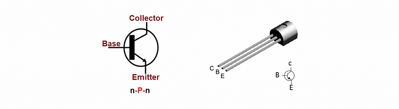
It is easy to remember the three corresponding pinouts of the diagram if you keep remembering the following picture,

Now, let’s focus on the applications of the BJTs. In the present experiment, we are going to use the BJT as a switch.
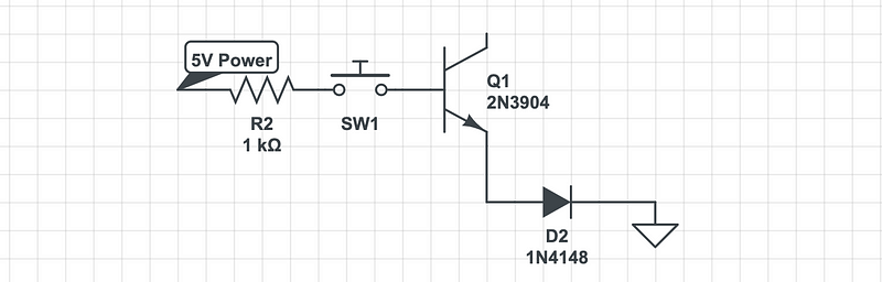
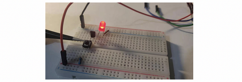
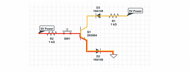
When the button is pressed, the LED will be lightened. The red line in the following shows the closed circuit.

Now, let’s add another LED to the connector pin (also add a resistor and a 5V power).
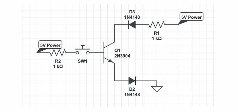
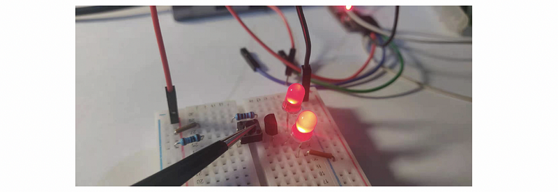
Then we press the button. Both of the LEDs are lightened and it is obvious that the D2 LED is even brighter than the D3 LED. This is because that there are two currents (shown by the red line and the yellow line) flow through the D2 LED but there’s merely a single current (the yellow line) that flows through the D3 LED.
Now, it may seem useless that we have a 5V Power on the left of the diagram. If we remove the 5V power on the left, then both of the LEDs will be unpowered even though it seems that the circuit is still perfectly closed and powered by the 5V source on the right side.
The reason for this is that the 5V power on the left actually acts as a switch of this circuit. If there is HIGH to the base pin, then the collector pin will be connected to the emitter pin. If there is LOW to the base pin, then the collector pin will be broken from the emitter pin.
The application of this is that we can use the signal to the base pin to control the connection between the collector pin and the emitter pin.
Okay, cool! In the next experiment, we are going to create a blinking light based on this feature of the BJT.