Computer Systems Experiments 13 | An Introduction of The 4-Digit 7-Segment Display
Computer Systems Experiments 13 | An Introduction of The 4-Digit 7-Segment Display
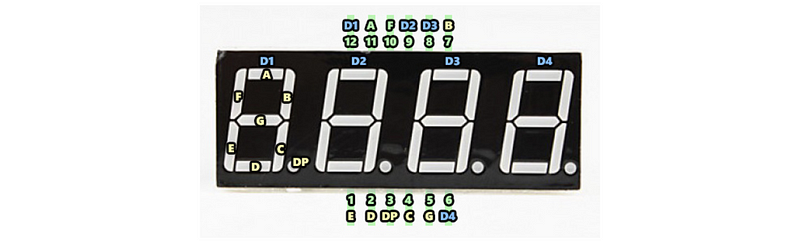
The 4-digit 7-segment Display is actually a bunch of LEDs (8 × 4 = 32 LEDs), so the usage of this electronic component is similar to the usage of LEDs. You may find that there are 12 pins in total (with 6 pins on the each side) and each of these pins serves a specific function.
The name of the pins follows the following diagram. You don’t need to know the meaning of them now, just to remember their names and the positions.
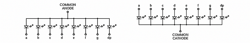
You may notice that we have used the common cathode display and you may know that there’s also another kind of display of common anode. What’s the difference between them? Well, we have known that each LED has two pins, one is called the anode pin (connected to the source) and the other is called cathode pin (connected to the ground). The common anode display means that all the anode pins of a digit is connected together, while the common cathode means the opposite case. You can better understand them from the following diagrams.
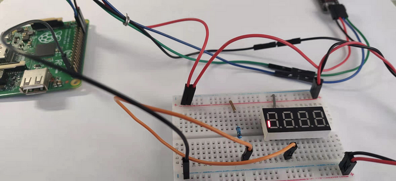
Now, let’s give it a try. Let’s connect the E pin (the pin connected all the anode pins of the E LEDs) to the 1k resistor and then connect to the 5V source. The D1 pin (the common cathode pin of the first digit) should be connected to the ground. Then,

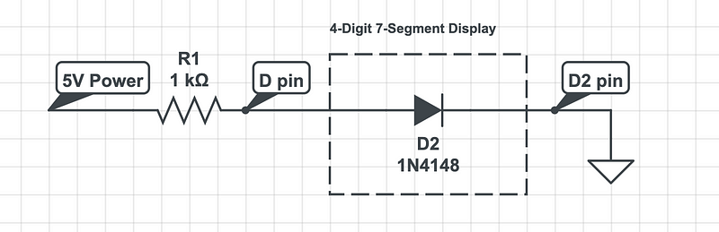
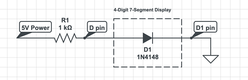
Also, if we change the input pin to the D pin, then,
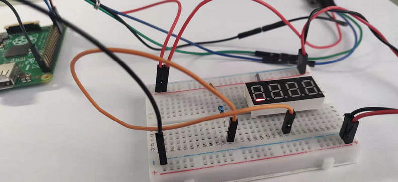
If we then change the output pin to the D2 pin, then,