Computer Systems Experiments 16 | 0 To 9 Counter
Computer Systems Experiments 16 | 0 To 9 Counter
In this experiment, we are going to control the 7 LEDs of the last digit (on the right side) in C language. The last digit will count from 0 to 9.
- Set the pointer to the register
The pointer in C is a variable being used to store the direct address of the memory location. Suppose we have a variable named VAR, and then we can extract the data on that memory by,
*VAR
Also, for a given variable DATA, we can extract the address of it by,
&DATA
To declare a pointer data type, we should add an * after the declaration of the data type stored. For example, if we want to define a pointer PT pointing to the int typed data DATA, then,
int *PT = &DATA
Or, if we want to directly assign an address to a pointer, we have to use the type conversion to change a hexadecimal value to an address,
int *PT = (int *) 0xffffffff
Recall, we have stored the address of the FSEL, SET, and CLR registers in the assembly by,
FSEL2: .word 0x20200008
SET0: .word 0x2020001C
CLR0: .word 0x20200028
Now, in the C language, we are going to assign these values with pointers. If we declare the data to be an int , then the highest bit will then be used to mean the sign of this value. Because all the bits for the register have a meaning of controlling the LEDs and we don’t want to mess up the things, we have to use unsigned int as our data type. Thus, the equivalent code in C should be,
static volatile unsigned int *FSEL2 =  (unsigned int *)0x20200008;
static volatile unsigned int *SET0  =  (unsigned int *)0x2020001c;
static volatile unsigned int *CLR0  =  (unsigned int *)0x20200028;
2. Set the delay time
In the assembly language, we have used,
.equ DELAY, 0x3F0000
to assign a value. For C, we can also similarly define this value by,
#define DELAY 0x3f0000
3. Construct the main function
We have talked about the C functions in the last experiment and for the C language, the main function is where a C program starts by default. From the main function, let’s first assign the functions of the GPIOs. For GPIO 20–26, let’s set them all to be output ,
*FSEL2 = 0b1001001001001001001;
Then, for different digits, we have to use different rules for LEDs. For example, we have to set HIGH to the ABCDEF pins and set LOW to the G pin to create a 0 digit. A reference diagram is as follows,

Then, for the number 0 to 9, we have the following series of rules,
int digit0 = 0b111111;
int digit1 = 0b110;
int digit2 = 0b1011011;
int digit3 = 0b1001111;
int digit4 = 0b1100110;
int digit5 = 0b1101101;
int digit6 = 0b1111101;
int digit7 = 0b111;
int digit8 = 0b1111111;
int digit9 = 0b1101111;
After this, we are going to construct an infinite while loop for the counting program,
while (1) {}And for displaying each digit, we have to left shift all the digits by 20 bits and then assign this value to the SET0 register. Then we use the for loop to delay a certain time and finally, the same value should be assigned this value to the CLR0 register to wrap the result. For instance, to display the digit 0,
*SET0 = digit0 << 20;
for (int c = DELAY; c != 0; c--) ;
*CLR0 = digit0 << 20;
In conclusion, the overall program is,
static volatile unsigned int *FSEL2 =  (unsigned int *)0x20200008;
static volatile unsigned int *SET0  =  (unsigned int *)0x2020001c;
static volatile unsigned int *CLR0  =  (unsigned int *)0x20200028;
#define DELAY 0x3f0000
void main(void) {
 // set GPIO 20-26 to output
    *FSEL2 = 0b1001001001001001001;
// assign the rules for displaying digits
int digit0 = 0b111111;
int digit1 = 0b110;
int digit2 = 0b1011011;
int digit3 = 0b1001111;
int digit4 = 0b1100110;
int digit5 = 0b1101101;
int digit6 = 0b1111101;
int digit7 = 0b111;
int digit8 = 0b1111111;
int digit9 = 0b1101111;
while (1) {
        *SET0 = digit0 << 20;
        for (int c = DELAY; c != 0; c--) ;
        *CLR0 = digit0 << 20;

        *SET0 = digit1 << 20;
        for (int c = DELAY; c != 0; c--) ;
        *CLR0 = digit1 << 20;
*SET0 = digit2 << 20;
for (int c = DELAY; c != 0; c--) ;
*CLR0 = digit2 << 20;
        *SET0 = digit3 << 20;
        for (int c = DELAY; c != 0; c--) ;
        *CLR0 = digit3 << 20;
        *SET0 = digit4 << 20;
        for (int c = DELAY; c != 0; c--) ;
        *CLR0 = digit4 << 20;
        *SET0 = digit5 << 20;
        for (int c = DELAY; c != 0; c--) ;
        *CLR0 = digit5 << 20;
        *SET0 = digit6 << 20;
        for (int c = DELAY; c != 0; c--) ;
        *CLR0 = digit6 << 20;
        *SET0 = digit7 << 20;
        for (int c = DELAY; c != 0; c--) ;
        *CLR0 = digit7 << 20;
        *SET0 = digit8 << 20;
        for (int c = DELAY; c != 0; c--) ;
        *CLR0 = digit8 << 20;
        *SET0 = digit9 << 20;
        for (int c = DELAY; c != 0; c--) ;
        *CLR0 = digit9 << 20;
    }
}
And you can also find this program from my repo. The electronic diagram of this experiment is as follows,
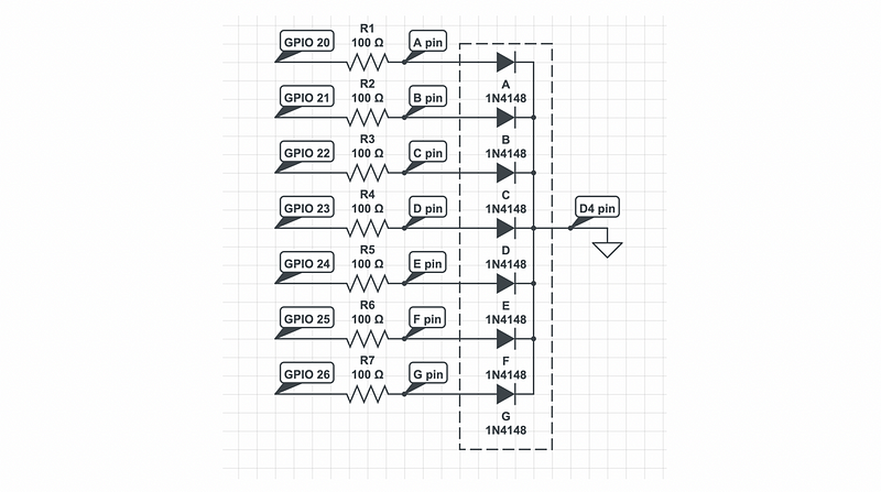
And note that the LEDs in this gif are for decoration (or debugging) purpose and you don’t have to include them in your circuit.