Computer Systems Experiments 17 | Vertical Counter
Computer Systems Experiments 17 | Vertical Counter

In this experiment, we are going to create a vertical counter counting from 0 to 3. The final result of this experiment should be,
Note that the red, green, and yellow LEDs are for the decoration (or debugging) purpose and you can omit them in your circuit.
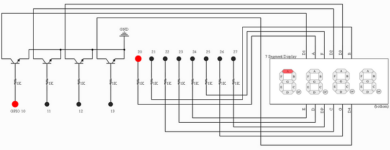
To achieve this goal, let’s recall the digital switch function of the BJTs. To control the 4 digits, we have to connect them to the four collector pins of the BJTs and then the 4 emitter pins should be connected to the ground because the 7-segment display is common cathode.
The 4 base pins of the BJTs should be connected to the GPIO 10–13, respectively, so that we can control whether or not to display the digits with the electronic level at the GPIO 10–13 pins.
Thus, the diagram should be,
In the last experiment, we assign digit rules to different variable named digit0 to digit9 . In this experiment, we are going to put them together as a single variable named digit .
int digit[] = {
    0b111111,
    0b110,
    0b1011011,
    0b1001111,
    0b1100110,
    0b1101101,
    0b1111101,
    0b111,
    0b1111111,
    0b1101111};
Then, it’s more convenient to use the digit0 to digit9 because,
digit[0] == digit0
digit[1] == digit1
...
digit[9] == digit9
And we can also use i (an int) to represent the ith digit,
digit[i]
Finally, for displaying these digits, we can use an infinite while loop. Also note that we should also set the GPIO 10–13 by,
while (1) {
    for(int i = 0; i < 4; i++){
        *SET0 = (digit[i] << 20) + (1 << (10+i));
        for (int c = DELAY; c != 0; c--) ;
        *CLR0 = (digit[i] << 20) + (1 << (10+i));
    }
}
In conclusion, the overall program is,
static volatile unsigned int *FSEL1 =  (unsigned int *)0x20200004;
static volatile unsigned int *FSEL2 =  (unsigned int *)0x20200008;
static volatile unsigned int *SET0  =  (unsigned int *)0x2020001c;
static volatile unsigned int *CLR0  =  (unsigned int *)0x20200028;
#define DELAY 0x3f0000
void main(void) {
    // set GPIO 10-13 to output
    *FSEL1 = 0b1001001001;
    // set GPIO 20-26 to output
    *FSEL2 = 0b1001001001001001001;
// assign the rules for displaying digits
int digit[] = {
0b111111,
0b110,
0b1011011,
0b1001111,
0b1100110,
0b1101101,
0b1111101,
0b111,
0b1111111,
0b1101111};
while (1) {
        for(int i = 0; i < 4; i++){
            *SET0 = (digit[i] << 20) + (1 << (10+i));
            for (int c = DELAY; c != 0; c--) ;
            *CLR0 = (digit[i] << 20) + (1 << (10+i));
        }
    }
}
You can also find this code from my repo.