Computer Systems Experiments 20 | Modular GPIO Design
Computer Systems Experiments 20 | Modular GPIO Design

In the previous experiments, we have used the pointers to set and clear values. However, the pointers are not easy to use and we may find ourselves debugging for a long time. So in this experiment, we are going to construct a GPIO model for us so that we can develop useful functions and also reuse the code for the other experiments.
To start with this experiment, we have to pull the starter code from the clock-starter repo. In this repo, you can find Makefile that is used for compiling and a src folder that contains our starter code.
In the src folder, you can find 4 folders,
appscontains a file namedclock.cthat we are going to implement in the following experiments.bootcontains three files:cstart.c,start.s, andmemmap. Thememmapthe file is used by the linker when building the program andstart.sandcstart.cprovide the minimum startup to set up a C program to run in the bare metal environment. Feel free to look into the files now to get a sneak preview, but don’t worry if you don’t fully understand them yet. We will discuss them in more detail soon.libcontains three files:gpio.c,abort.c, andtimer.c. The filegpio.cis the file that we are going to implement in this experiment and the filetimer.cis the file for the next experiment. Theabort.cfile is used for asserting the execution of the test.testscontains the testing filetest_gpio_timer.cand in this experiment, we are going to configure this file in order to add more tests.
The direction file of this experiment is the header file of the gpio.c , which is named gpio.h . You can find this file from the environment folder. The path to gpio.h on my computer is,
~/ComputerSysE/environment/include/gpio.h
Now, let’s start. The first operations we are going to implement are gpio_set_function and gpio_get_function. These operations use the FSEL device registers to configure the mode of a GPIO pin.
0. Testing the result
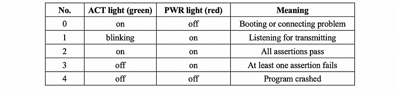
The assert() function in the testing file test_gpio_timer.c drives the red and green LEDs on the Pi as a simple status indicator. If an assertion fails, the program halts and blinks the red LED (for me, it is not blinking but shining) of doom. If all asserts pass and the program finishes normally and the green LED of happiness will turn on. Your goal is to make that little green light shine. Here is a reference table for a quick check,
To test our result, we have to use the command,
$ make test
gpio_set_functionImplementation
First of all, we have to make sure that the parameter pin and function are all valid. We can check values by,
if (!(pin >= GPIO_PIN_FIRST && pin <= GPIO_PIN_LAST)) return;
if (!(function >= GPIO_FUNC_INPUT && function <= GPIO_FUNC_ALT3)) return;
Or, we can also do,
if (pin < GPIO_PIN_FIRST || pin > GPIO_PIN_LAST) return;
if (function < GPIO_FUNC_INPUT || function > GPIO_FUNC_ALT3) return;
Note that the upper bound condition of the function parameter is GPIO_FUNC_ALT3 instead of GPIO_FUNC_ALT5. You can find form the gpio.h that GPIO_FUNC_ALT3 = 7 and GPIO_FUNC_ALT5 = 2 .
Then, we have to find the FSEL register we would like to assign. We can get a pointer to the target FSEL register based on the value of pin .
volatile unsigned int *FSEL = FSEL_BASE + (pin / 10);
Note that,
FSEL_BASE + (pin / 10)
doesn’t mean to add pin/10 directly. When we add a int value to a pointer variable, it actually follows the rule of,
(unsigned int *) ((int) FSEL_BASE + (pin / 10) * sizeof(unsigned int))
In this case, the size of an unsigned variable is 4, so we don't have to multiply 4 to pin / 10 .
The following question can be a little bit tricky. How can we set the value of the given pin without impacting the other pin functions? Let’s, first of all, try. the OR operation. For example, if we want to change a function from 0b001 to 0b111 ,
  Origin: 0000 0000 0000 1000
Function:             11 1
  Target: 0000 0000 0011 1000
Okay, we can find out it works well in this case, but to think about another example. Let’s say we would like to change 0b111 to 0b001 , then
  Origin: 0000 0000 0011 1000
Function:             00 1
  Target: 0000 0000 0011 1000
the OR operation no longer works. The same situation happens to the AND operation, so we can not achieve our goal merely by a single operation. Here, we are going to introduce the mask method. For any of the given origin, let’s first clear the target pin function to 000 without impacting the other functions (by a mask), and then we can use the OR operation to assign the value. To use this method, let’s first calculate the offset value of our given pin by,
int offset = (pin % 10) * 3;
Then, we can use our method to reset the value.
*FSEL = *FSEL & ~(0b111 << offset);
*FSEL = *FSEL | (function << offset);
2. gpio_get_function Implementation
Again, we have to make sure the pin is valid,
if (!(pin >= GPIO_PIN_FIRST && pin <= GPIO_PIN_LAST)) return GPIO_INVALID_REQUEST;
Note that we have to return GPIO_INVALID_REQUEST when the pin is not valid. We can extract the function of a pin by its offset value and then extract the last three bits of the result after a right shifting,
return (*FSEL >> offset) & 0b111;
3. gpio_write Implementation
Because we are using the SET register, the offset is no longer calculated by (pin%10)*3 . Instead, it can be calculated by,
int offset = pin % 32;
When value is 1, that means we have to set the value of the SET register. When value is 0, we have to set the value of the CLR register. We can use a conditioned structure for this,
if (value) {
   volatile unsigned int *reg = SET_BASE + (pin / 32);
   *reg = (1 << offset);
}
else {
   volatile unsigned int *reg = CLR_BASE + (pin / 32);
   *reg = (1 << offset);
}
Note that we can not write the program like,
if (value) {
   volatile unsigned int *reg = SET_BASE + (pin / 32);
}
else {
   volatile unsigned int *reg = CLR_BASE + (pin / 32);
}
*reg = (1 << offset);
Because this function will not know the reg variable outside the {} sign.
Also, we can directly use 1 << offset and there is no need to worry about the impact of the other pins. This is because we can only set the output of a pin to HIGH by SET so 0 will not influence the other outputs.
4. gpio_read Implementation
It is quite similar to read from the function. To read from a pin, the pin should be set to input (we don’t have to check this) and we should read from the LEV register. The level of a pin is only the last bit after offsetting,
return (*LEV >> offset) & 0b1;
In conclusion, the overall program gpio.c can be found in my repo.
5. Testing the result
To test our result, we have to uncomment the test_gpio_set_get_function(); and test_gpio_read_write(); in the main function of the testing file test_gpio_timer.c ,
void main(void) {
    test_gpio_set_get_function();
    test_gpio_read_write();
    // test_timer();
}
Also, the tests in the function test_gpio_set_get_function() can not cover all the cases. We can add the following assertions to test for the integrity of the features,
// Confirm setting a GPIO pin to alternate function modes,
// not just input or output
// test 1
gpio_set_function(GPIO_PIN2, GPIO_FUNC_INPUT);
assert( gpio_get_function(GPIO_PIN2) == GPIO_FUNC_INPUT );
// test 2
gpio_set_function(GPIO_PIN2, GPIO_FUNC_ALT5);
assert( gpio_get_function(GPIO_PIN2) == GPIO_FUNC_ALT5 );
// test 3
gpio_set_function(GPIO_PIN2, GPIO_FUNC_ALT0);
assert( gpio_get_function(GPIO_PIN2) == GPIO_FUNC_ALT0 );
// test 4
gpio_set_function(GPIO_PIN2, GPIO_FUNC_ALT3);
assert( gpio_get_function(GPIO_PIN2) == GPIO_FUNC_ALT3 );
// Confirm can configure a GPIO pin in each of the different
// FSEL registers
gpio_set_output(GPIO_PIN12);
assert( gpio_get_function(GPIO_PIN12) == GPIO_FUNC_OUTPUT );
gpio_set_output(GPIO_PIN22);
assert( gpio_get_function(GPIO_PIN22) == GPIO_FUNC_OUTPUT );
gpio_set_output(GPIO_PIN32);
assert( gpio_get_function(GPIO_PIN32) == GPIO_FUNC_OUTPUT );
gpio_set_output(GPIO_PIN42);
assert( gpio_get_function(GPIO_PIN42) == GPIO_FUNC_OUTPUT );
gpio_set_output(GPIO_PIN52);
assert( gpio_get_function(GPIO_PIN52) == GPIO_FUNC_OUTPUT );
// Confirm no interference when configuring multiple GPIO
// pins within the same FSEL register
gpio_set_output(GPIO_PIN12);
gpio_set_output(GPIO_PIN13);
gpio_set_output(GPIO_PIN14);
assert( gpio_get_function(GPIO_PIN12) == GPIO_FUNC_OUTPUT );
assert( gpio_get_function(GPIO_PIN13) == GPIO_FUNC_OUTPUT );
assert( gpio_get_function(GPIO_PIN14) == GPIO_FUNC_OUTPUT );
// Confirm that improper requests are gracefully handled
assert( gpio_get_function(70) == GPIO_INVALID_REQUEST );
assert( gpio_get_function(-10) == GPIO_INVALID_REQUEST );
// Random tests
gpio_set_function(GPIO_PIN31, GPIO_FUNC_ALT5);
gpio_set_function(GPIO_PIN24, GPIO_FUNC_ALT3);
gpio_set_function(GPIO_PIN50, GPIO_FUNC_ALT2);
assert( gpio_get_function(GPIO_PIN31) == GPIO_FUNC_ALT5 );
assert( gpio_get_function(GPIO_PIN24) == GPIO_FUNC_ALT3 );
assert( gpio_get_function(GPIO_PIN50) == GPIO_FUNC_ALT2 );
gpio_set_function(GPIO_PIN11, GPIO_FUNC_ALT5);
gpio_set_function(GPIO_PIN12, GPIO_FUNC_ALT3);
gpio_set_function(GPIO_PIN13, GPIO_FUNC_ALT2);
gpio_set_function(GPIO_PIN16, GPIO_FUNC_ALT4);
gpio_set_function(GPIO_PIN17, GPIO_FUNC_OUTPUT);
assert( gpio_get_function(GPIO_PIN11) == GPIO_FUNC_ALT5 );
assert( gpio_get_function(GPIO_PIN12) == GPIO_FUNC_ALT3 );
assert( gpio_get_function(GPIO_PIN13) == GPIO_FUNC_ALT2 );
assert( gpio_get_function(GPIO_PIN16) == GPIO_FUNC_ALT4 );
assert( gpio_get_function(GPIO_PIN17) == GPIO_FUNC_OUTPUT );
You can also find this completed testing file from my repo.