High-Performance Computer Architecture 14 | Tomasulo’s Algorithm Part 2
High-Performance Computer Architecture 14 | Tomasulo’s Algorithm Part 2

- Load & Store Instructions
(1) Dependencies for Memory
Just like we have the data dependencies for the registers, there can be dependencies through memory.
- RAW Dependency: First
SW(store) to addressA, thenLW(load) from it. - WAR Dependency: First
LWfrom addressA, thenSWto it. If weLWagain, we will get a value different from before. - WAW Dependency: Conduct
SWtwice to the same addressA. Because we want the final value in the memory to be the value from the laterSW, we have to keep the order of these twoSWs.
(2) Tomasulo’s Algorithm for Memory Dependencies
Basically, we have two ways to deal with the memory dependencies,
- Loads and stores are in-order
For all the load and store instructions, we first put them in the load or store queue (buffer) and then we just follow the order of these instructions. For example, a load doesn’t execute if there is a previous store pending, even though the load is ready to go but the store is still waiting.
- Identify dependencies and reorder them
This turns out to be more complicated than doing it for register-based dependencies. This is not the approach that we have chosen for Tomasulo’s algorithm, but this dependencies identification is actually used by the modern processors that we are going to talk about later.
2. Tomasulo’s Algorithm: A Complex Example
(0) Basic Settings
Suppose we have the following assembly code and .D means double-precision,
L.D F6, 34(R2)
L.D F2, 45(R3)
MUL.D F0, F2, F4
SUB.D F8, F2, F6
DIV.D F10, F0, F6
ADD.D F6, F8, F2
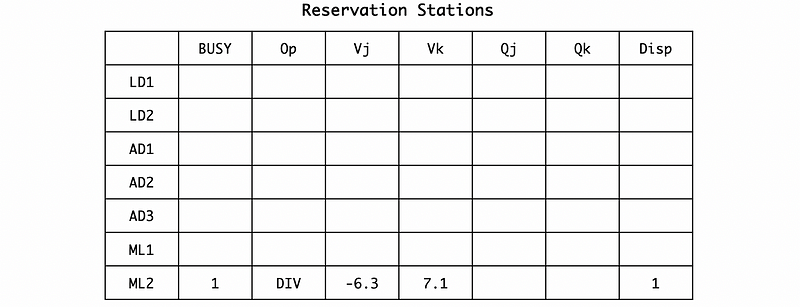
Suppose we have 2 load and store reservation stations LD1 and LD2, 3 add and subtract reservation stations AD1, AD2, and AD3, and 2 multiple and divide reservation stations ML1 and ML2. We use BUSY to represent whether or not a reservation station is empty, Op for the operation, Vj for the first operand, Vk for the second operand, Qj for the first operand we are waiting for, Qk for the second operand we are waiting for, and Disp means whether or not this instruction can be dispatched.
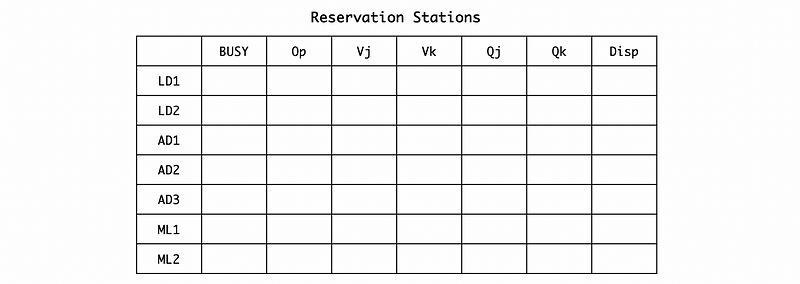
Also, we have to consider the execution cycles. In reality, we need more than 1 cycles for any arithmetic operations. Particularly, in this case, the cycles we need for these arithmetic operations are,
Load:  2 cycles
 Add:  2 cycles
 Mul: 10 cycles
 Div: 40 cycles
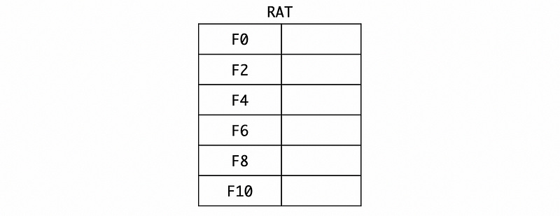
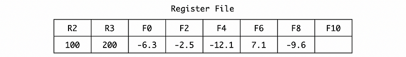
We also have to know about the think about the register file. Originally, the R2 is set to 100, R3 is set to 200, and F4 is set to 2.5. The other registers are left empty.

Also, the RAT should be kept empty,
(1) Cycle 1
In cycle 1, the L.D F6, 34(R2) is issued to the reservation station. Because the address generation unit is independent, so we can directly get the value of R2 + 34 = 134.
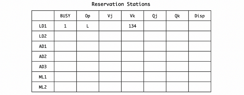
Also, because the value returned will be assigned to F6, thus, we should rename the F6 to LD1 by RAT,

(2) Cycle 2
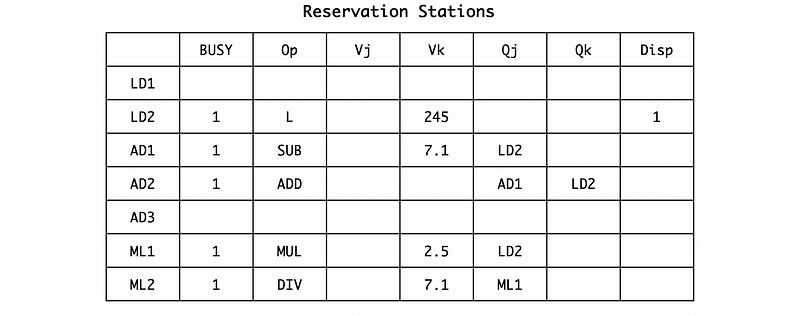
In cycle 2, the L.D F2, 45(R3) is issued to the reservation station and we can directly get the value of R3 + 45 = 245. We should also dispatch the LD1 because it is ready after the first cycle. Note that we need 2 cycles to finish the load execution.
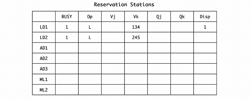
Also, the RAT should map F2 to LD2.

(3) Cycle 3
In cycle 3, the MUL.D F0, F2, F4 is issued to the reservation station. When it is issued, according to the RAT, F2 is mapping to LD2, and F4 has a direct value 2.5 on RF. So the second operand Vk should be assigned to 2.5 and the first operand we are waiting for Qj should be assigned to LD2. Because the execution unit of the LD1 is still working, so we will not dispatch any instruction in this cycle.
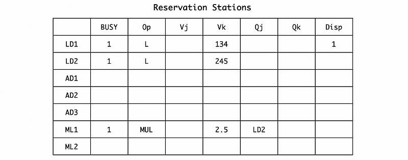
Also, we have to rename F0 to ML1 by RAT,

(4) Cycle 4
In cycle 4, the SUB.D F8, F2, F6 is issued to the reservation station. Similarly, we can have (if we do not consider the dispatching and broadcasting now),
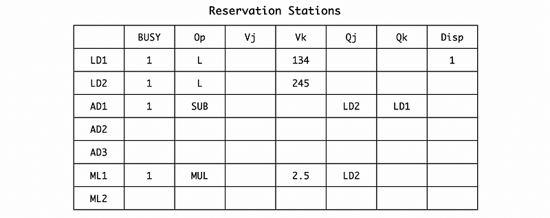
Also, we should rename F8 to AD1 by RAT,

Because it is already 2 cycles since we execute the first instruction. So the LD1 is finished and LD2 can be dispatched to the execution unit. ML1 can not be dispatched because it is still waiting for the result of LD2 in the register station. For the broadcasted result, let’s say the result of LD1 is 7.1. Because the result of LD1 is being broadcasted, of course, it will not be busy in the reservation station. Then,
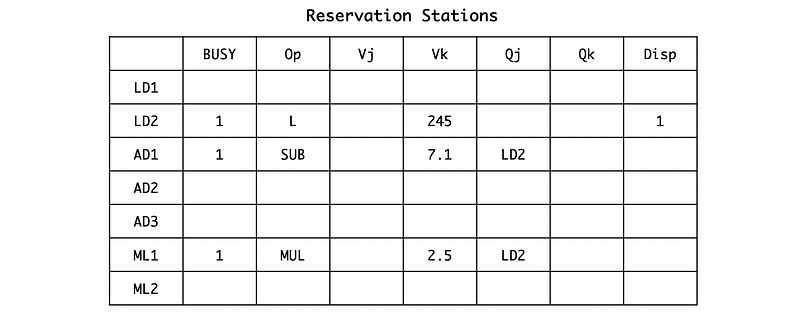
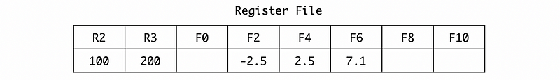
So after broadcasting, the register file is now,

And the RAT should be,

(5) Cycle 5
In cycle 5, the DIV.D F10, F0, F6 is issued to the reservation station. Similarly, we can have (if we do not consider the dispatching and broadcasting now),
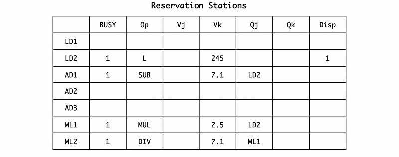
Also, we should rename F10 to ML2 by RAT,

If the dispatching and broadcasting are concerned, we can find out that because we are still executing the LD2, we can not dispatch or broadcast anything because all the instructions in the reservation stations are waiting for some results.
(6) Cycle 6
In cycle 6, the ADD.D F6, F8, F2 is issued to the reservation station. Similarly, we can have (if we do not consider the dispatching and broadcasting now),
Also, we should rename F6 to AD2 by RAT,

Now, let’s consider dispatching and broadcasting. First of all, the result of LD2 (let’s say -2.5) will be broadcasted so the operands waiting for LD2 in the register station will be replaced by this result. Also, because the LD2 register station is no longer busy, we can release the occupation of LD2.
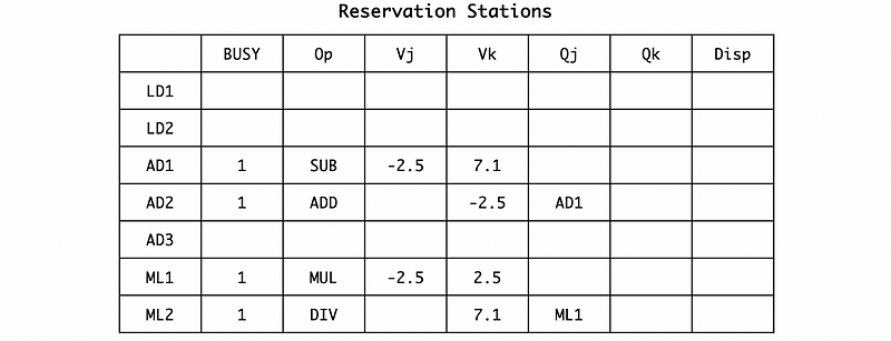
After broadcasting, the register file is now,
And the RAT should be,

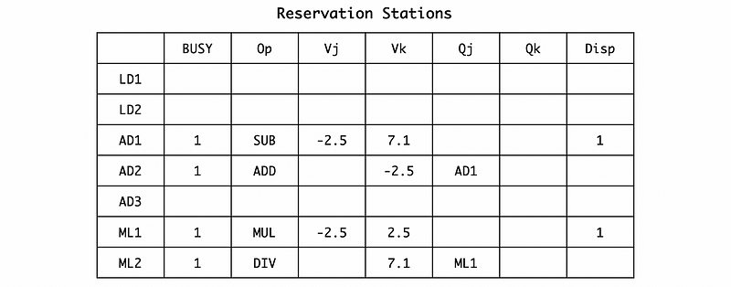
Under the condition that we can not capture a result and then dispatch the instruction in the same cycle, so we have to wait for the next cycle to dispatch AD1 and ML1.
(7) Cycle 7
Because there are no instructions in the instruction queue, we are not going to issue any new instructions since the present cycle. However, both AD1 and ML1 can be dispatched. We need 2 cycles for AD1 to complete and 10 cycles for ML1 to complete.
Because there’s no broadcasting, we don’t have to change the RF and RAT.
(8) Cycle 9
There is nothing specific for cycle 8, but for cycle 9, the execution of AD1 finishes and the result should be broadcast. The AD1 reservation station will be released, and the result of AD1, which is -9.6 would be broadcasted to both the reservation station and the RAT & RF. For the reservation station, AD2 is waiting for the result of AD1, so its operand will be updated.
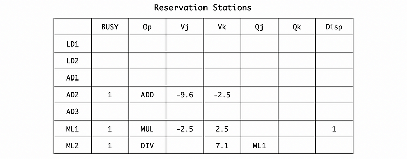
According to RAT, the result of AD1 should be set to F8. So we should update the F8 register in the RF and then empty the F8 entry of RAT. The register file should be,

The RAT should be,

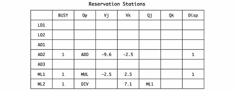
(9) Cycle 10
In cycle 10, the AD2 instruction will be dispatched and its execution will be finished in cycle 12.
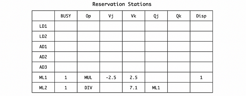
(10) Cycle 12
In cycle 12, the execution of AD2 will be finished. So the result will be broadcasted. Then the reservation station will be,
The register file would be,

And the RAT would be,

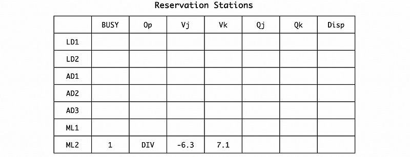
(11) Cycle 17
In cycle 17, the instruction ML1 will be finished and its result -6.3 will be broadcasted. So the reservation station will be,
The register file would be,
And the RAT would be,

(12) Cycle 18
In cycle 18, the ML2 instruction will be dispatched and the execution will be finished in cycle 58 (18 + 40).
(13) Cycle 58
In cycle 58, the result -0.2 of the instruction ML2 will be broadcasted. So, the reservation station will be empty. The register file would be,

And RAT will also be empty.
3. Timing Shortcut
Sometimes we don’t want to write down the whole example because it can be quite complex. Commonly, we just want to get the time (number of cycles) that we are going to have for issuing, executing, or writing result for an instruction. Actually, we can have a shortcut to calculate the timing.
ISSUING EXECUTION WRITING-RESULT
The issue can be written in the first place because we can issue as much as possible until all the reservation stations we need (for our instruction type) are filled. We can simply enumerate all the instructions from 1 to the filled count.
ISSUING       EXECUTION      WRITING-RESULT
1
2
3
4
5
6
WAIT
Then let’s find out the data dependencies. For our previous program,
L.D F6, 34(R2)
L.D F2, 45(R3)
MUL.D F0, F2, F4
SUB.D F8, F2, F6
DIV.D F10, F0, F6
ADD.D F6, F8, F2
So we have, I3 depends on I2; I4 depends on I1 and I2; I5 depends on I1 and I3 ; I6 depends on I2 and I4.
Thus, we must run the code with the sequence of,
I2 -> I3
I1 / I2 -> I3 -> I5
I1 / I2 -> I4 -> I6
Then we can find out that I1 and I2 should be executed first if we want to execute the other instructions. We have known that they are both L.D instructions and they will take 2 cycles for execution. So the difference between writing and execution is 2.
ISSUING       EXECUTION      WRITING-RESULT
1             2              4
2             4              6
3
4
5
6
After we finish I1 and I2, we can now dispatch both I3 and I4 (because they require different ALUs) in the next cycle. I3 needs 10 cycles to finish and I4 needs 2 cycles to finish. So,
ISSUING       EXECUTION      WRITING-RESULT
1             2               4
2             4               6
3             7              17
4             7               9
5
6
After I4 is finished, I6 can be dispatched in the next cycle (10) and it tasks 2 cycles to finish. So,
ISSUING       EXECUTION      WRITING-RESULT
1              2              4
2              4              6
3              7             17
4              7              9
5
6             10             12
After I3 is finished, I5 can be dispatched in the next cycle (18) and it tasks 40 cycles to finish. So,
ISSUING       EXECUTION      WRITING-RESULT
1              2              4
2              4              6
3              7             17
4              7              9
5             18             58
6             10             12