High-Performance Computer Architecture 35 | Final Review
High-Performance Computer Architecture 35 | Final Review

- Cache
(1) Locality
- Temporal Locality: If an address has been accessed recently, it will likely be accessed again
- Spatial Locality: If an address has been accessed, it is likely that addresses close to it will be accessed
(2) AMAT

(3) Miss Time

(4) General AMAT

(5) Block Size
Block size is the amount of data stored for each memory address.
(6) Block Number and Block Offset
The memory address can be divide into two parts, the block number, and the block offset.
- Block number is used to determine which block in the cache should be accessed.
- Block offset is used to determine which part of a block should be the data of that memory address.

(7) Tags
Tags are used to determine which block should be accessed, it must contain at least one bit from the block number.
(8) Valid Bit
The valid bit should be used in the cache for showing the validity of the cached data.
(9) Directed Mapped Cache (DMC)
More than one memory block will be mapped to the same cache line.
- Block offset is the data location in the cache line
- Index decides which cache line we will direct to
- Tag finds out if this line matches the current memory block

But this DM cache will result in a higher cache miss rate.
(10) Cache Miss
Because more than one block can be mapped to the same cache line, the previous data would be kicked out from the cache and thus we will have a cache miss.
(11) Set Associative Cache (SAC)
In the set-associative cache, the cache lines are divided into several sets and each set has a bunch of cache lines. This means that more than one memory block will be mapped to the same cache set.
- Block offset is the data location in the cache line
- Index decides which cache set we will direct to
- Tag finds out if this line matches the current memory block
If we have N cache lines in a set, then this SAC is called an N-way set-associative cache. By the way, the DMC can be treated as an extreme case of 1-way set-associative cache. When we have only a single set in the cache, and this means that each memory block can be mapped into any cache line, this SAC is called a fully set-associative cache.
(12) Cache Replacement Policies
When the set is full, we have to kick out a block in a cache line to make room for the new one. The cache replacement policies are the methods for choosing the block to kick out.
- Random
- FIFO: track the oldest one
- least recently used (LRU): add LRU counter for each cache line
- not most recently used (NMRU): track only the MRU block, and randomly kicks out one of the NMRU lines
- Pseudo LRU (PLRU): PLRU counters start with zeros, change to 1 if a line is recently used. Randomly kick out a 0 counter line, if all 1, then zero out all the PLRU counters.
(13) LRU Implementation
For the value in the LRU counter,
- LRU = 0
- MRU = N, which is the number of cache lines in this set
We have to update the LRU counters every we access a set.
(14) LRU Cost
For an N-way set-associative cache, the cost of each LRU counter should be log2(N) bits, and thus, the cost for each set should be Nlog2(N) bits.
If there are M sets in an N-way set-associative cache, then the general cost for maintaining the LRU policies should be MNlog2(N) bits.
(15) Write-Allocate Cache
Most caches today are write-allocated caches. This means that the block is written to the cache after each writes if we have a cache miss. This is because we want to benefit from the locality.
(16) Non-Write-Allocate Cache
If the block is not written to the cache after each writes, we will result in a non-write-allocate cache.
(17) Write-Through Cache
If the main memory is updated immediately when the cache is updated, then we will have a write-through cache. This is unpopular because the cost and traffic on the bus will be high.
(18) Write-Back Cache
In a write-back cache, the block is only written to the memory when the block is replaced from the cache.
(19) Pipelined Cache
The pipelined cache means that we will separate the cache hit into stages so as to overlap with another cache hit. There are three stages for a cache hit,
- reading the set index
- determining cache hit and start data read
- finish data read
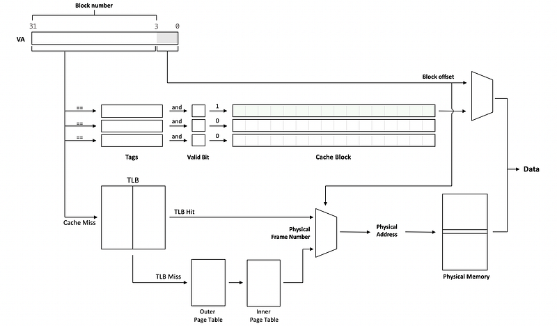
(20) VIVT Cache
If the virtual address is used by the cache, then it is called a virtually accessed cache, or a virtually indexed, virtually tagged cache (or VIVT cache). Here are some features,
- the virtual page number is used for tagging
- the virtual page number is used for cache indexing
- the virtual page number is used for TLB indexing
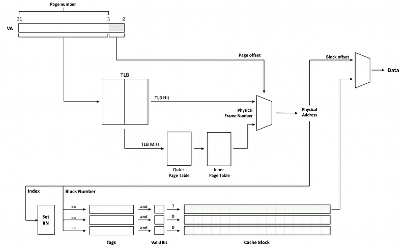
(21) PIPT Cache
A cache that uses the physical addresses is called a physically indexed, physically tagged cache (or PIPT cache or physically accessed cache). Here are some features,
- the physical page number is used for tagging
- the physical page number is used for cache indexing
- the virtual page number is used for TLB indexing
(22) VIPT Cache
The VIPT cache is a combination of the VIVT and PIPT caches, which has the following features,
- the physical page number is used for tagging
- the virtual page number is used for cache indexing
- the virtual page number is used for TLB indexing
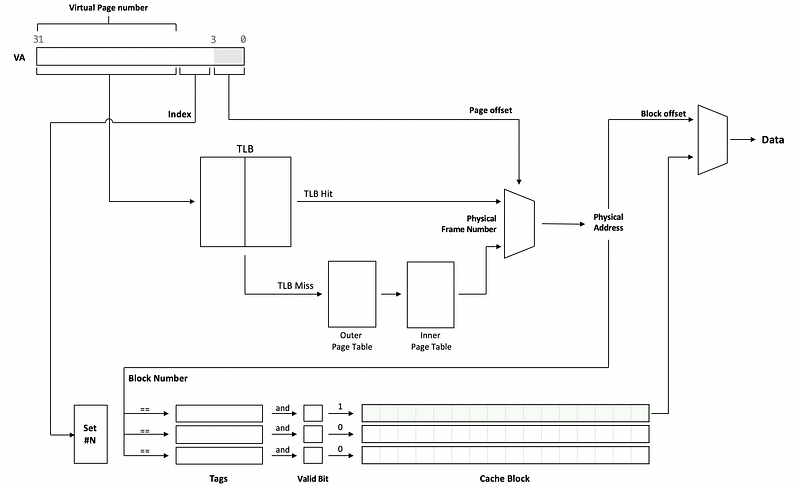
This cache is designed to conduct the cache lookup and the V2P translation at the same time. Also, the same physically tagged can be mapped to the same cache block and the cost for storage can be reduced.
(23) Calculating VIPT L1 Cache Size
- Page size -> Page offset bits
- Block size -> Block offset bits
- Index size bits = Page offset bits - Block offset bits
- Set Number = 2^Index size bits
- General Size = Set Number * Block size * Cache lines per set
As a quick calculation, we can use the formula,

(24) Way Prediction
With way prediction, the processor tries to guess which set is most likely to be a hit. All kinds of SACs can benefit from this method but the DMC does not.
(25) Types of Cache Misses
- Compulsory Miss: when a block is accessed for the first time, and this will happen even for an infinite cache
- Capacity Miss: blocks evicted when the cache is full. This is because we have a limited cache size.
- Conflict Miss: blocks are evicted due to associativity. This is because we have limited associativity.
(26) Prefetching
Prefetching means that we will prefetch blocks into the cache to improve the cache miss rate.
(27) Cache Pollution
When we make some bad prefetching guesses, we will result in cache pollution because we prefetch the stuff that is not useful in the future.
(28) Prefetching Methods
We can use different methods for prefetching,
- software prefetching: This means the compiler will add prefetching instructions
- stream buffer hardware prefetching: This means simply prefetch next blocks
- stride hardware prefetching: This means it will prefetch the blocks with a fixed distance
- correlating hardware prefetching: This means it will prefetch the blocks based on some correlating rules
(29) Loop Interchange
This means reorganizing the loop in order to benefit from the spatial locality. This is done by the compiler.
(30) Overlap Misses
Using non-blocking that supports hit-under-miss and miss-under-miss instead of blocking cache.
(31) Miss Status Handling Registers (MSHRs)
MSHRs are the registers to determine if we have a true miss or if we have a half-miss (means that we have a miss but the data is already loaded by some other instruction, and the loading process does not finish). Here are some features,
- MSHR is released when the data arrives from the memory.
- Normally we would have 16–32 MSHRs
(32) AMAT and Cache Hierarchy
This means that we can have multi-level caches. The miss penalty for each level will be,

And the LLC (last level cache) AMAT should be,

Therefore, the general AMAT will be,

(33) Global Miss Rate of a Cache
Memory references == Memory accesses,

(34) Local Miss Rate of a Cache

(35) Local Hit Rate of a Cache

(36) Misses Per Thousand Instructions (MPKI)
This is another metric for the number of misses per 1,000 instructions.
(37) Inclusion Property
The same block can be in or not in different level of caches,
- Inclusion: means that this block is also in the L2 cache
- Exclusion: means that this block is not in the L2 cache
- Random: means that this block may or may not be in the L2 cache
(38) Summary: Methods for Reducing Hit Time
- overlap cache hits by Pipelined caches
- overlap cache hit with TLB hit by VIPT
- guess the hit set by way prediction
- implement replacement policies like NMRU and PLRU
(39) Summary: Methods for Reducing Miss Rate
- Having large cache blocks to benefit from spatial locality
- Prefetch blocks to reduce future cache misses
- Reorganize loops to benefit from locality by loop interchange
- overlap the hits and misses by non-blocking cache and MSHRs
(40) Summary: Methods for Reducing Miss Penalty
- reduce the miss penalty overall by having cache hierarchies
Example 1-1. SA Cache, Index, and Offsets
The processor has a 32Kbyte, 32-way set associative, write-back, write-allocate, virtually indexed, physically-tagged L1 cache with 64-byte blocks. The system uses 32-bit virtual and physical addresses, with 4K byte pages.
a. Can we overlap virtual-to-physical address translation with the L1 cache access? Explain your answer.
b. Each time the processor accesses the cache, what is the number of tag comparisons that are needed to determine if the access is a cache hit?
c. If the processor reads memory at virtual address 0x00001234 (physical address 0xFFFF1234), what is the index that is used to access the cache?
d. If the processor reads memory at virtual address 0x00001234 (physical address 0xFFFF1234), what is the tag that is used by the cache to determine if the access is a cache hit?
Solution:
Summary of the cache is,
- 32 KB size
- 32-way SAC
- write allocate and write back
- VIPT
- 64-byte blocks: means a 6-bit block offset
- 4Kb page: means a 2-bit page offset
- Index bits: 32KB / 32 way / 64 Byte = 16 sets, means we have 4 bits for index
a. Yes. Because the block offset bits plus the number of index bits is less than the number of the page offset bits, the index can be obtained from the physical address, so overlap of address translation and cache access can occur.
b. 32, because we have a 32-way SAC means that there will be 32 block tags we need to compare
c. The page offset should be,
0x1234
The binary page offset should be,
0001 0010 0011 0100
The block offset should be the last 6 bits,
110100
And the index should be,
1000
In hexadecimal format, the index should be,
0x8
d. Except for the index and the block offset, the rest should be the tag. Because we have a VIPT cache, we need to generate tags based on the physical address, so the tag should be
1111 1111 1111 1111 0001 00
And this is also,
0011 1111 1111 1111 1100 0100
In hexadecimal format, the tag should be,
0x3FFFC4
Example 1-2. SA Cache, Index, and Offsets
Consider an 8-way set-associative 32KB, VIPT, write-back, write-allocate L1 data cache with an LRU replacement policy. Each block has a size of 32 bytes and the system uses 32-bit virtual and 56-bit physical addresses. The bits of an address are numbered from 0 (least-significant bit) to 31 (or 55 for physical address).
a. When accessing this cache, different parts of the virtual and physical address are used at different times.
First, we use the ___________ (bits ___ through ____) from the ______________ address to ______________________________.
Second, we use the _________ (bits ___ through ____) from the ______________ address to ______________________________.
Finally, we use the _________ (bits ___ through ____) from the ______________ address to ______________________________.
b. For each 32-byte block of data in the cache, some extra bits (metadata) are kept in the cache. What are these bits and how many meta-data bits altogether does each cache block have?
Solution:
a.
First, we use the index (bits 5 through 11) from the virtual address to find which set to look at.
Second, we use the tag (bits 12 through 55) from the physical address to check if any blocks in the set have a matching tag.
Finally, we use the offset (bits 0 through 4) from the virtual address to get the right byte in the block.
b.
- Valid bit: 1 bit/line
- Dirty bit: 1 bit/line
- LRU counter: log2(8) = 3 bit/line
- Tag: 44 bit/line (56–12 = 44 bit)
Altogether, we have 49-bit metadata in each cache line.
Example 1-3. Cache Misses
A processor has a 16-way set-associative, write-back, write-allocate, physically indexed, 4kB cache with 16-byte lines. Starting with an empty cache (all lines invalid), the processor begins zeroing out the elements of an array that begins at physical address 0x40fbfca8 and is 0x4000 bytes long. Pages are 1MB in size. Each element of the array is four bytes in size and the processor writes a zero into each element from first to last, without accessing any other memory locations.
a. By the time the zeroing-out is done, how many cache misses will have occurred?
b. Which set in the cache will be the first one to not have any non-valid (empty) lines left?
c. By the time the zeroing-out is done, how many write-backs will have occurred?
d. What is the tag of the last cache line to be written back to memory?
Solution:
The cache summary is,
- 4kB size
- 16 bytes per line, means the block size is 16 bytes
- block offset is 4 bit (0~3 bit)
- 256 lines
- 16-way SAC
- 16 sets: 4-bit index (4~7 bit)
a.
- Array length 0x4000 bytes, all of them will be cache misses when the first access
- If aligned, we can have 0x4000 / 16 = 0x400 = 1024 times cache misses
- If not aligned, we need to have one more block, so there will be 1025 times cache misses
Because the block offset is of the starting address is,
0x8
This means we are not aligned and there will be 1025 times cache misses.
b.
The first set that is accessed is the first one to become full because we have a round-robin set access rule. The starting address is,
0x40fbfca8
The index is,
0xA = 10
So we have the conclusion that the 10th set will be the first one to not have any non-valid (empty) lines left.
c.
In the end, the last 256 lines of data will not be kicked out and we can keep them in the cache. However, there have to be 1025 lines of data (as we have discussed in a.). So the number of writing back to the memory is,
1025 - 256 = 769
d.
The last cache line is the 768th line, so the starting address of this line is,
0x40fbfca8 + 768 * 16 = 0x40fbfca8 + 0x3000 = 0x40fc2ca8
Except for the 0~3 bit as the block offset and the 4~7 bit as the index, the rest of the address will be the tag. Therefore, the tag of the last cache line to be written back to memory is,
0x40fc2c
Example 1-4. SA Cache, Index, and Offsets
The Processor has a 32Kbyte, 4-way set associative, write back, write allocate, physically indexed, physically tagged L1 cache with 32-byte blocks. The system uses 32-bit virtual and physical addresses with 4 Kbyte pages.
a. Can we overlap virtual-to-physical address translation with the L1 cache access? Explain your answer.
b. The designers of this cache had a very good reason for not making it a virtually indexed, physically tagged cache. What is the reason?
c. If the processor reads memory at virtual address 0x00001234 (physical address 0xFFFF1234), what is the index that is used to access the cache?
d. If the processor reads memory at virtual address 0x00001234 (physical address 0xFFFF1234), what is the tag that is used by the cache to determine if the access is a cache hit?
e. If the processor reads memory at virtual address 0x00001234 (physical address 0xFFFF1234), how many tag comparisons are done to determine if the access is a cache hit?
Solution:
a. No. Because the cache is physically indexed and it needs a physical address to start lookup.
b. Aliasing. We will result in different values for the same memory address.
c. The physical address is,
1111 1111 1111 1111 0001 0010 0011 0100
The block offset should have 5 bits,
10100
There are 256 sets so the index should be an 8-bit index,
1 0010 001
d. The rest of the physical address should be the tag,
1111 1111 1111 1111 000
e. Because we have a 4-way SAC, then the tag comparison we have to done is 4.
2. Memory and Virtual Memory
(1) Virtual Memory
The program thinks that it virtually has a lot of memory. But in practice, there isn’t that much memory. The technique to deceive the programs that we have enough memory is called virtual memory.
(2) Pages
The virtual memory is divided into small blocks (commonly 4KB per page) called pages.
(3) Frames
The physical memory is divided into small blocks (commonly 4KB per frame) called frames.
(4) Page Number and Page Offset
Similar to the cache blocks, the virtual address can also be divided into two parts.
- Page offset (LSB): Page offset is the data location in the frame
- Virtual page number (MSB): Virtual page number should be translated to physical frame number before we can determine which frame should be the data of that memory address

(5) Flat Page Table
In order to conduct V2P translation, we can maintain a table for translating the virtual page number to the physical frame number. The simplest idea is to maintain a flat page table with all the V2P mappings kept in one single table. Here are some features of this table,
- Size: # of pages in VM times the size per entry in the flat page table

- Indexing: The virtual page number is used to index the flat page table
- Advantages: Simple and easy
- Disadvantages: Costly and Unnecessary
(6) Multi-Level Page Tables (MLPT)
Especially when we have a large virtual memory, multi-level page tables can be useful because we can hide some of the useless V2P mappings. This is also called a hierarchical page table.
- Indexing: The page number is partitioned into the inner page number and the outer page numbers. The outer page numbers are used to index the outer page tables and the inner page number is used to index the inner page table. For instance, the following virtual address can be an example.
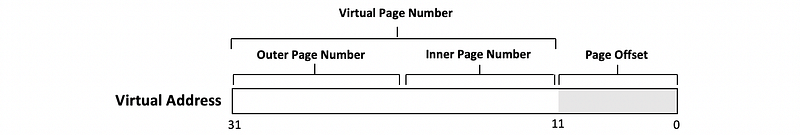
- Advantages: The cost for storage is lower
- Disadvantages: Slow because we have to read through the page table entries
(7) Table Look-Aside Buffer (TLB)
To speed up the V2P translation, a special, small cache is used called the table look-aside buffer (aka. TLB). This table is always fully associative with 64~512 entries.
3. Memory
(1) Random Access Memory (RAM)
Random-access memory (RAM) simply refers to the fact that we can access any memory location by address without going through all the memory locations.
(2) Statistic Random Access Memory (SRAM)
The term “statistic” refers to the fact that SRAM retains its data while the power is supplied. This is faster and more expensive.
(3) Dynamic Random Access Memory (DRAM)
The term “dynamic” means that we will lose data unless we refresh the data. This is slower.
(4) Memory Cell
The smallest unit in the memory we use to keep the data.
(5) Word Lines
Lines used to activate memory cells.
(6) Bit Lines
Lines used to input the data to the memory cell. These lines are perpendicular to the word lines.
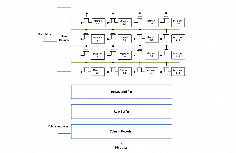
(7) Row Decoder
This decides which word line gets activated.
(8) Column Decoder
It selects the correct bits among the bit lines using the column address and then it outputs a single bit.
(9) Row Address
The input to the row decoder implies which word line to be activated.
(10) Column Address
The input to the column decoder implies the correct bits among the bit lines.
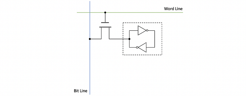
(11) SRAM Implementation
In SRAM, the actual memory cell consists of two CMOS inverters.
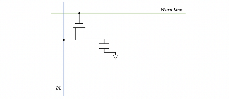
(12) DRAM Implementation
In SRAM, the memory cell only consists of a capacitor that is used to keep the value of the data.
(13) Destructive Read
Because of the transistor leakage, the capacitor drains into the bit line but it is no longer fully charged. This is called a destructive read.
(14) Trench Cell
In real DRAM, the capacitor and the transistor are built as a signal transistor in a technology called trench cell.
(15) Sense Amplifier
This architecture connects all the bit lines. It senses the small changes on the bit lines and amplifies them.
(16) Row Buffer
This a storage element that stores the correct values read from the whole row of cells after amplified by the sense amplifier.
(17) A 16-bit Memory Chip Organization
(18) Memory Read Pattern: Read-then-Write
When we read from the memory, we will first read the data and then the data will be written back to the corresponding row. This means that after each read, the data will be refreshed to avoid destructive read.
(19) Memory Write Pattern: Read-then-Write
The writing process is similar to read, and we have to read the data firstly to the row buffer, then change some values, and finally write the data back.
(20) Fast-Page Mode
If we first read/write a row, and then we immediately read/write it again, we will enter the fast-page mode of this row. This means that we can directly read/write from the row buffer.
(21) Front-Side Bus
DRAM is access to the processor through the front-side bus using a memory controller.
4. Storage and Fault Tolerance
(1) Types of the Storage
- Magnetic disks: HDD and floppy disks
- Optical disks: such as CDs or DVDs
- Tape: for backup
- Flash drivers: much faster
(2) Platters
The platters in the disks are used to keep the data on both of its surfaces.
(3) Spindle
All the platters are attached to a single spindle.
(4) Magnetic Head
Heads are used to read the data from the platters.
(5) Head Assembly
All the heads are connected together to the head assembly.
(6) Tracks
Each magnetic head will be able to access a circle called track on the surface of the disk.
(7) Cylinder
All of the tracks at the same distance from the spindle is called a cylinder.
(8) Sectors
The data along with one track is divided into different sectors, and the sector is the smallest unit we can read. A sector will consist of three parts,
- Preamble: Used to tell where should the sector start
- Data
- Checksum
(9) Magnetic Disk Capacity

(10) Magnetic Disk Access Time
- Spinning time: time to spin the platters
- Seek time: time to find the cylinder
- Rotational latency: time to move to the correct sector
- Data read: time to read data
- Controller time: time to check data
- I/O bus time: time to send data to the processor
- Queuing delay: time to wait for a previous read
(11) Solid-State Disk (SSD)
SSD can be a DRAM and battery. It is fast but expensive.
(12) Flash Memory
It works like SSD without a power supplier.
(13) Hybrid Magnetic Flash
The flash memory is combined with the traditional HDD as a cache.
(14) Buses for Storage I/O
- I/O Buses
- Mezzanine Bus: like PCI expresses, SATA, and SCSI
(15) Dependability
Qualify if a delivered service that justifies relying on the system to provide the service.
(16) Specified Service Vs. Delivered Service
- Specified Service: the expected system behavior
- Delivered Service: the actual system behavior
(17) Fault
Modules deviate from the specified behaviors. This is also called a latent error.
(18) Error
The actual behavior within the system differs from the specified behavior. This is also called an active fault.
(19) Failure
The failure occurs when the system deviated from the specified behavior.
(20) Reliability
A measure of continuous service accomplishment. This can be measured by mean time to failure (or MTTF).
(21) Mean Time to Failure (MTTF)
The MTTF is how long will the system provide service before the next service interruption.
(22) Availability
The availability measures service accomplishment as a fraction of the overall time. This can be measured by,

(23) Types of Faults
- Hardware (HW) faults: hardware fails to perform as designed
- Design faults: software bugs or the hardware design mistakes
- Operation faults: operator or the user’s mistakes
- Environmental faults: fire and the power failure
- Permanent faults: once we have it, it doesn’t get corrected
- Intermittent faults: last for a while but recurring
- Transient faults: last for a while and then go away
(24) Checkpointing
The checkpointing saves the state periodically, then if we detect the errors, we will stop the system and restore the state.
(25) 2-way Redundancy (DMR)
Two modules do the exact same work, and the outcomes are compared. Rollback and recovery if the outcomes are different.
(26) 3-way Redundancy (TMR)
Three modules do the exact same work, and the outcomes are voted. Expensive but it can tolerate one fault in one module.
(27) 5-way Redundancy
Five modules do the exact same work, and the outcomes are voted. Expensive but it can tolerate one fault in 2 modules.
(28) Error Correction Methods
- Parity Bit: XOR all the data bits
- Error-Correction Code (ECC): SECDED can correct up to 1-bit flip
- Redundant Array of Independent Disks (RAID): a technique family for error correction
(29) RAID Overview
- RAID 0: striping
- RAID 1: mirroring
- RAID 4: block interleaved parity (BIP)
- RAID 5: distributed block interleaved parity
- RAID 6: two parity blocks
(30) Failure Rate
In the following discussion, we will suppose the failure rate of a disk is f.
(31) RAID 0
RAID 0 takes N disks as a single disk, and the tracks will be referred to as strips. The reliability will become worse because,

(32) RAID 1
With RAID 1, the other disks are copies of the first disk. Suppose we have N disks with the same copy, then without replacement, the MTTDL (mean time to data loss) will be,

With replacement, the MTTDL will be,

(33) RAID 4
It adds an additional disk used for keeping the XOR results of strips as parities. For N disks in RAID 4, there will be,
- N-1 disks for striped data
- 1 disk for parity blocks
Because now we can tolerant one disk failure, then without replacement,

With replacement, the MTTDL will be,

Although the read throughput will be N-1 times a single disk, the write throughput will be 1/2 because both data and parity should be written.
(34) RAID 5
RAID 5 is implemented with a distributed block interleaved parity. The read throughput will be N times the throughput of a single disk, and the write throughput will be N/4 times the throughput of a single disk.
(35) RAID 6
RAID 6 can still work with 2 failed strips. When
- one disk fails: use the parity bit to recover
- two disks fail: use equations to reconstruct the data
Example 4-1. Disk and RAID
A 6,000RPM disk drive has 5 platters, with 100,000 tracks per surface, 1,000 sectors per track, and 512 data bytes per sector. Each sector also has a 128-bit error detection code that can detect all errors in its sector but cannot correct any errors. The head takes one microsecond (one-millionth of a second) to move from one cylinder to an adjacent cylinder, and multi-cylinder movements are done at the same speed (one cylinder per microsecond). The disk controller is very fast (assume zero latency for everything it does) and the I/O bus has a very large (assume infinite) bandwidth.
a. How many heads does the disk drive have?
b. Assuming that the disk controller and the drive itself are not servicing any other requests, what is the worst-case time needed to read a sector from the disk?
c. Assuming that the disk controller and the drive itself are not servicing any other requests, what is the best-case time needed to read the entire disk?
d. If we use two of these disk drives in a RAID0 configuration, what is the total data capacity of the resulting RAID array?
e. If we use two of these disk drives in a RAID0 configuration, can we recover all data if one sector is damaged on one of the disk drives? Explain your answer.
f. If we use two of these disk drives in a RAID1 configuration, can we recover all data if one disk drive is accidentally dropped into an active volcano? Explain your answer.
g. If we use five of these disk drives in a RAID5 configuration, what is the total data capacity of the resulting RAID array?
h. If we use five of these disk drives in a RAID5 configuration, is it possible to damage only two sectors in a way that the RAID array cannot recover from? Explain your answer.
Solution:
A summary of the HDD is,
- 6,000RPM
- 5 platters
- 100,000 tracks per surface
- 1,000 sectors per track
- Each sector contains a 128-bit ECC detecting all errors
- Head move time: 1us per cylinder
- infinite I/O bus bandwidth
a. 10, because we have 5 platters and each of them has 2 sides. We need to adopt a head for each side.
b. In the worst case,
- One track is #0 and another is #100,000. We have to move the head in 99,999 us = 0.099999 s.
- We are writing after the start of the sector we want, so we have to wait for another 1000 sectors to get to the same position. This is 1 rotation. After that, we have to read the data from this sector. So we need to go through 1001 sectors and it takes 1.001 rotations. By the fact of 6000 RPM, we can calculate the time we need for this 1.001 rotation, which is 1.001 / (6000/60) = 0.01001 s.
This in general, the overall time we need for reading this sector is
0.099999 + 0.01001 = 0.110009 s
c. In the best case of reading the entire disk,
- One time one direction head movement: from track #0 to track #100,000. We have to move the head in 99,999 us = 0.099999 s.
- Go through all the sectors in sequence and we have to spend 1 rotation for each track. Overall, we need to rotate 100,000 times and the time of it will be 1000 s.
This in general, the overall time we need is
1000 + 0.099999 = 1000.099999 s
d. In RAID 0, these two disks will be treated as a whole disk. So the capacity will be 2*1000*100000*512 = 1024 * 10⁹ bytes
e. Because there is no redundancy for RAID 0, we can not recover data.
f. Yes because each of the individual disks will contain all the data. The other one acts like a redundancy.
g. In RAID 5, except for the disk that is used to store the parity data, the other 4 disks can be treated as a single disk. So the capacity will be 4*1000*100000*512 = 2048 * 10⁹ bytes
h. If we have one-bit flip problems on two different disks, even though we can know which disk has the error, we can not recover from this error by parity.
Example 4–2. Disk and RAID
A 12,000 RPM disk drive has 2 platters, with 100,000 tracks per surface, 1,000 sectors per track, and 512 data bytes per sector. Each sector also has a 128-bit error detection code that can detect all errors in its sector but cannot correct any errors. The head takes ten microseconds (a 100,000thcylinder, and multi-cylinder movements are done at the same speed (100,000 cylinders per second). The disk controller is very fast (assume zero latency for everything it does) and the I/O bus has a very large (assume infinite) bandwidth.
a. How many heads does the disk drive have?
b. Assuming that the disk controller and the drive itself are not servicing any other requests, what is the worst-case time needed to read a sector from the disk?
c. If we use two of these disk drives in a RAID0 configuration, and if the array is full (it contains as much data as its capacity allows), what is the best-case time needed to read all of the data stored in the array?
d. If we use five of these disk drives in a RAID5 configuration, and if the array is full (it contains as much data as its capacity allows), what is the best-case time needed to read all of the data stored in the array?
e. If we use three of these disk drives in a RAID5 configuration and we are extremely lucky, what is the maximum number of sectors that can be damaged in this array that still allow us to recover all of the data?
Solution:
A summary of the HDD is,
- 12,000 RPM
- 2 platters
- 100,000 tracks per surface
- 1,000 sectors per track
- 512 data per sector
- Each sector contains a 128-bit ECC detecting all errors
- Head move time: 10us per cylinder
- infinite I/O bus bandwidth
a. 4, because we have two platters
b. For the worst case,
- Move from track #0 to track #100,000, which needs time for moving 99,999 tracks and the time is 999,990 us = 0.99999 s.
- Read 1001 sectors, which means to have 1.001 rotation. The rotation time we need is 1.001 / (12,000 /60) = 1.001/200 = 0.005005 s.
Thus, the overall time we need is 1.004995 s.
c. For the best case, both disks can be read simultaneously and we only have to consider one disk
- Move from track #0 to track #100,000, which needs time for moving 99,999 tracks and the time is 999,990 us = 0.99999 s.
- Each track has a rotation, so there will be 100,000 rotations. The time for this will be 100,000/ (12,000 /60) = 500 s
Thus, the overall time we need is 500.99999 s.
d. In the best case,
- Move from track #0 to track #100,000, which needs time for moving 99,999 tracks and the time is 999,990 us = 0.99999 s.
- We will skip reading the parity so that only 4/5 of each disk is read. The time for this will be 4/5 * 500 = 400 s.
Thus, the overall time we need is 400.99999 s.
e. We can recover when we have errors only in one disk. In the maximum case, all the data in that disk were damaged. So the maximum number of damaged sections we can have is the number of all the sections on a disk.
4 * 100,000 * 1,000 = 400,000,000 sectors
5. Cache Coherence
(1) Snooping
All writes are put on the shared bus, and the cores snoop the bus for updating caches.
(2) Directory
Each block state is maintained by a directory, which reflects the state change after each writes. This is useful for more than 8 cores. A directory has the following features,
- distribute across all cores
- each core has its own slice
- each slice serve a set of blocks
(3) Write-Updating
Broadcast all write values so other cores can update the cache lines.
(4) Write-Invalidate
Broadcast all writes to make other copies of that data invalid in the other caches.
(5) Dirty Bit
Dirty bit is used to show that the current modification of the cache line hasn’t been written to the memory.
(6) Valid Bit
The valid bit is used to show whether the current cache is valid for reading.
(7) Shared Bit
The shared bit is used to show whether the data in the current cache line is shared with some other caches.
(8) MSI Coherence Protocol
In MSI, a block can be in one of three states in a cache,
- Invalid state (I): Valid bit = 0, when the block is not in any caches
- Shared state (S): Valid bit = 1; Dirty bit = 0, when the block is in the cache and not modified
- Modified state (M): Valid bit = 1; Dirty bit = 1, then the block is in the cache and it is modified
When a read happens, we are expecting,
I -> S, S -> S, M -> M
When a write happens, we are expecting,
S -> I, I -> M, S -> M, M -> M
When writing back to the memory, we are expecting,
M -> I
(9) MOSI Coherence Protocol
MOSI is implemented to perform the cache to cache transformation and avoid writebacks to the memory for read-after-write.
- Owner state (O): this means that the block is in the cache and is modified. It will provide this data to the other caches instead of from the memory.
So when a read happens, we are expecting,
I -> S, S -> S, M -> O, O -> O
When a write happens, we are expecting,
S -> I, O -> I, I -> M, S -> M, M -> M
When writing back to the memory, we are expecting,
M -> I, O -> I
(10) MOESI Coherence Protocol
MOESI is implemented to unnecessary traffic for S -> I when a block write happens.
- Exclusive State (E): this means that the block is in the cache and is modified. But it is not shared with any other caches so we don’t have to send invalidation traffics on the bus.
So when a read happens, we are expecting,
I -> E, I -> S, S -> S, M -> O, O -> O, E -> E, E -> S
When a write happens, we are expecting,
S -> I, O -> I, I -> M, S -> M, M -> M, E -> M
When writing back to the memory, we are expecting,
M -> I, O -> I
(11) Directory Entry
A directory entry has,
- 1 dirty bit
- 1 bit for showing the cache is present (1) or not present (0)
(12) Coherence Miss
The coherence miss happens because we invalidate some blocks in the cache to maintain the cache coherence.
(13) True Coherence Miss
When different cores accessing the same data, we can have true coherence miss.
(14) False Coherence Miss
When different cores access different data and there should not be any coherence messages because of that, except for these data items are in the same block.
Example 5-1. MESI Protocol
A shared-memory bus-based multiprocessor has two processors. Each processor has a direct-mapped L1 cache, with only sixteen 256-byte blocks in each cache. All addresses in this problem are physical addresses, and all caches are physically indexed and tagged. The MESI coherence protocol is used in this multiprocessor. The current state of the two caches is:
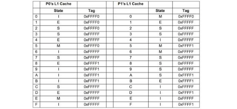
If the next access is each one of the following instructions, answer do we need to access result in a bus broadcast and what will be the new content of the corresponding lines in P0 and P1 caches.
a. a P0 access which executes SB (store byte) to address 0xFFFFFCFF
b. a P1 access which executes SB (store byte) to address 0xFFFFF5FF
c. a P1 access which executes LB (load byte) to address 0xFFFFF3FF
d. a P0 access which executes SB (store byte) to address 0xFFFFFD00
e. a P0 access which executes SB (store byte) to address 0xFFFFF700
Solution:
The cache summary,
- 256-byte block size: 8-bit block offset
- 16 blocks in cache: 4-bit index
- 2 processors
- only L1 DM Cache
- PIPT
- MESI
a. Yes, because S->M must invalidate others.
P0
--------------------
C     M      0xFFFFF
P1
--------------------
C     I      0xFFFFF
b. Yes, because write back to memory
P0
--------------------
5     M      0xFFFF0
P1
--------------------
5     M      0xFFFFF
c. No, S->S with no need to broadcast on the bus
P0
--------------------
3     S      0xFFFFF
P1
--------------------
3     S      0xFFFFF
d. No, E->M with no need to broadcast because the current block is exclusive
P0
--------------------
D     M      0xFFFFF
P1
--------------------
D     I      0xFFFF1
e. Yes, S->M and we have to invalidate others
P0
--------------------
7     M      0xFFFFF
P1
--------------------
7     I      0xFFFFF
Example 5–2. MESI Protocol
A shared-memory bus-based multiprocessor has two processors. Each processor has a small direct-mapped L1 cache, with only two 8-byte blocks in each cache. All addresses in this problem are 12-bit physical addresses, and all caches are physically indexed and tagged. The MESI coherence protocol is used in this multiprocessor. The initial state for the two caches is with tags of 0 and in I state.
a. What is the shortest sequence of accesses that will start with the initial state and result in the following cache state:

b. What is the shortest sequence of accesses that will start with the initial state and result in the following cache state:

c. What is the shortest sequence of accesses that will start with the initial state and result in the following cache state:

d. What is the shortest sequence of accesses that will start with the initial state and result in the following cache state:

e. Explain why the following state can not happen,

f. Explain why the following state can not happen,

Solution:
Summary of the cache,
- L1 DMC
- 8-byte block size: 3-bit block offset
- PIPT with 12-bit physical addresses
- MESI
- 2 lines per cache: 1-bit index
a. X means any value
P0     RD     0000 0001 0XXX
P1     RD     0000 0001 0XXX
b.
P0     RD     0000 0001 0XXX
P1     WR     0000 0001 0XXX
c. This requires us first write back, then read again from the memory
P0     RD     0000 0001 0XXX
P1     WR     0000 0001 0XXX
P0     RD     0000 0010 0XXX     // kick out line 0
P0     RD     0000 0001 0XXX     // kick out line 0
d.
P0     RD     0000 0001 0XXX
P1     RD     0000 0001 0XXX
P1     RD     0000 0010 0XXX
e. To have a I state in the P1 cache, the line 0 in P0 must be in either M state (means that it validate line 0 in P1 cache like b.) or E state (means the data is written to the memory and then read again like c.)
f. To have I state in both cache lines, we need to have a write operation in another core. Because there are only two cores, then this case is impossible.
6. Memory Consistency
(1) Memory Consistency
Memory consistency determines the order of accesses by different cores, and it ensures that the program is the same as the execution order.
(2) Sequential Consistency (SC)
This is the simplest idea to make all the memory accesses in the program order by each processor. This will hurt the performance.
(3) Relaxed Consistency (RC)
We can release some of the rules in SC like a read-after-read operation. This is then called a relaxed consistency model.
(4) msync Instruction
X86 msync instruction can be used as a boundary for maintaining memory consistency.
(5) Data Race
This means the accesses to the same address by different cores that are not ordered by synchronization.
(6) Data-Race-Free Program
A data-race-free program is a program that can not create any data races in its executions with proper synchronizations.
7. Multiprocessing, Synchronization, Many Cores
(1) Flynn’s Taxonomy of Parallel Machines
- Single Instruction, Single Data (SISD): normal uniprocessor
- Single Instruction, Multiple Data (SIMD): vector processor
- Multiple Instruction, Single Data (MISD): stream processor
- Multiple Instruction, Multiple Data (MIMD): normal multiprocessor.
(2) Uniform Memory Access Time (UMA): sharing main memory
All cores have caches, but they will share the same main memory. Also called symmetric multiprocessor (SMP) or centralized shared memory. It works well for a small number of cores (<16).
(3) Non-Uniform Memory Access Time (NUMA): distributed memory
Each core will have its own cache and a slice of the main memory. Also called distributed shared memory.
(4) Message Passing
One way to communicate between processes is by passing messages. The hardware for this can be simple but programming can be hard.
(5) Shared Memory
Different cores can also communicate via the shared memory. We need synchronization (i.e. locking and unlocking) for the shared memory.
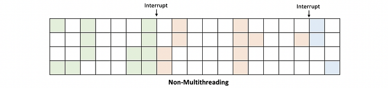
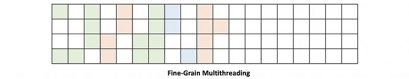
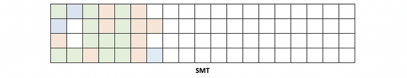
(6) Hardware Multithreading
The hardware multithreading can be,
- coarse-grain: means changing the threads every few cycles
- fine-grain: means to change threads every cycle
- simultaneous multithreading (SMT, or Hyper-threading): means that in any given cycle, we could be doing instructions that belong to different threads.
(7) SMT Hardware Requirements
- Add a program counter
- Add a RAT
- Add architectural registers
- Can not use VIVT
(8) Atomic Code Sections (Critical Sections)
These are the sections of code that must be executed completely one at a time.
(9) Mutual Exclusion (Mutex)
A type of synchronization used for atomic sections.
(10) Atomic Instructions
To implement a mutex, we must use some hardware-supported atomic instructions. There are mainly three types of them,
- Atomic exchange instructions
- Test-then-write family
- Load Link/Store Conditional (LL/SC) instructions
(11) Barrier
The barrier is another way to maintain synchronization, and this will be used when several threads are allowed to access an atomic section at a time. A typical barrier implementation has two variables,
- A counter: counts how many threads arrived
- A flag: gets set when the counter reaches N
typedef struct barrier_t {
    int count;
    int flag;
} barrier_t;
(12) Reuse Barrier: Flippable Local Sense
To solve the deadlock problem, we must reuse the barrier with flippable local sense. This means that after passing the first barrier, the local sense for the flag will be flipped.
(13) Many-Core Challenges
- Bus Bottleneck: we need efficient bus designs like mesh
- Off-Chip Traffic Bottleneck: we have to share the LLC or make it distributed
- Over Large Coherence Directory: conduct directory slicing or partial directory
- Power Budget for Cores: boost the frequency of the active cores
- OS Confusion: beyond our scope of discussion
Example 7-1. Parallel Processing
A shared-memory system with two processors is executing the following two code fragments in parallel (one on each processor). All variables are shared and are initially zeros. The system uses sequential consistency.
Processor 0 executes,
A = 10;
Atmp = A;
B = Atmp - 2;
while (C == 0);
C = 6;
printf("%d %d %d\n", A, B, C);
Processor 1 executes,
Btmp = B;
C = Btmp;
if(C == 0)
    C = 3;
A = 3;
a. Is it possible for the printout in P0 to be 10 8 6. If yes, show the execution interleaving that produces this printout. If no, explain.
b. Is it possible for P0 to get stuck and never print out anything? If yes, show the execution interleaving that produces this printout. If no, explain.
c. Is it possible for P0 to print 3 as the value of C? If yes, show the execution interleaving that produces this printout. If no, explain.
d. Is it possible for P0 to print a value of C other than 3 or 6? If yes, show the execution interleaving that produces this printout. If no, explain.
e. Is it possible for P0 to print a value of B other than 8? If yes, show the execution interleaving that produces this printout. If no, explain.
Solution:
a. Yes. A possible interleaving can be,
A = 10;                            // A = 10
Atmp = A;
B = Atmp - 2;                      // B = 8
Btmp = B;
C = Btmp;                          // C = 8
if(C == 0)
    C = 3;
while (C == 0);
C = 6;                             // C = 6
printf("%d %d %d\n", A, B, C);     // print
A = 3;
b. No. This is not possible because the P1 program will not be stuck and if it finds a C = 0, C will be assigned to 3. So that P0 can no longer be stuck in the while loop after that.
c. No. C will become 3 only if in the program P0 C is 0 before the if statement. But if C is not 0, it will pass the while loop and finally be set to 6 in the end. Therefore, we can not achieve a printout of 3 for C.
d. No. As we have said in C if C begins with value 0, we can not achieve a printout of C other than 6.
e. Yes. A possible interleaving can be,
A = 10;               // A = 10
Btmp = B;
C = Btmp;             // C = 0
if(C == 0)
    C = 3;            // C = 3
A = 3;                // A = 3
Atmp = A;
B = Atmp - 2;         // B = 1
while (C == 0);
C = 6;                // C = 6
printf("%d %d %d\n", A, B, C);         // print
In this case, the printout for B in P0 should be 1.
Example 7-2. Barrier
Two shared-memory systems use different implementations of the sense-reversal barrier:
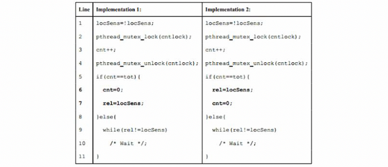
Variable locSens is local in each thread, and variable cntlock, cnt, tot, and rel are global variables shared by all threads. All these variables start out with zero values, except cntlock (which is correctly initialized using pthread_mutex_init).
Whereas Implementation 1 is correct, Implementation 2 does not. Show a (sequentially consistent) execution order for two threads (tot is 2) in Implementation 2 that leads to incorrect behavior.
An execution order (interleaving) can be represented as a sequence of [Core #: Line #] events, using “Work” instead of a line number for actual work between calls to the barrier, e.g. [C1: L1], [C2: L1], [C1: L2,L3,L4], [C2: L2,L3,L4], [C1: L5], [C2: L5], [C1: L6], [C2: L6], [C1: L7], [C2: L7], [C1: Work], [C2: Work], [C1: L1], [C2: L1], etc. leads to correct behavior.
Solution:
[C1: L1, L2, L3, L4, L5, L9]      // C1 waiting
[C2: L1, L2, L3, L4, L5, L6]      // C2 release the rel
[C1: L9]                          // C1 continue
[C1: Work]                        // C1 actual work
[C1: L1, L2, L3, L4, L5, L9]      // cnt == 3 without reset by C2
[C2: L7]                          // cnt == 0 reset by C2
[C2: Work]                        // C2 actual work
[C2: L1, L2, L3, L4, L5, L9]      // cnt == 1 so C2 have to wait
Because now both are waiting for each other at L9, this leads to incorrect behavior.
Final Example. Potpourri
True or False
- Increasing cache associativity reduces compulsory misses.
- A page fault requires a page table walk.
- Context switch requires TLB flush.
- For a highly irregular memory access pattern, the open-page DRAM policy will decrease the average DRAM access time.
- A system with an inclusive L2 cache has a higher effective capacity than a system with a non-inclusive L2 of the same size.
Solution:
- False. It will reduce conflict misses.
- False. A page fault means the page is not in the table and requires OS intervention to bring that page to DRAM after the page table walk.
- True. When we do context switch, we need to flush the whole TLB.
- False. An irregular memory access pattern will increase the average DRAM access time.
- False. An inclusive L2 cache has a lower effective capacity because it contains all the cache lines in the L1 cache.