Operating System 21 | Introduction to I/O Devices, CPU and Device Interactions, Virtual File…
Operating System 21 | Introduction to I/O Devices, CPU and Device Interactions, Virtual File System Abstractions, and Understanding Inode

- Introduction to I/O Devices
(1) The Definition of I/O Devices
As we can see, the execution of applications doesn’t rely only on the CPU and the memory, but it relies on many other different types of hardware components. Some of these components are specifically tied to provide inputs or outputs, or both are called I/O devices.
(2) Types of I/O Devices
There are a number of I/O devices that the operating system integrated into the overall computer system. The common I/O devices include,
- keyboards
- microphones
- displays
- speakers
- mice
- network interface card (NIC)
- hard disk
- USB flashcard
- etc.
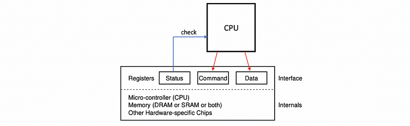
(3) Key Features of Any I/O Devices
Any device can be abstracted to have the following set of features,
- a set of control registers: includes status registers (for showing the CPU what’s happening on the device), command registers (what does the device do), data transfer registers (CPU controlled data transfer), etc. that can be accessed by the CPU and that permit the CPU device interactions
- a micro-controller: this is like a device’s CPU, and this is what controls all of the operations that actually take place on the device
- on-device memory (DRAM or SRAM or both): there will be some amount of memory for the device
- other logic: there will also be some other types of processing logic, special chips, or specialized hardware that is needed on the device

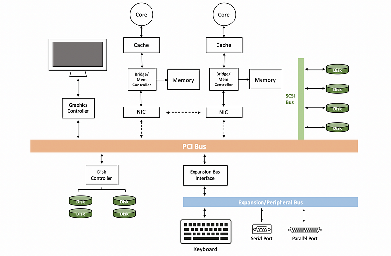
(4) The Definition of Peripheral Component Interconnect (PCI)
The PCI bus stands for the peripheral component interconnect bus, and it is one of the standard methods for connecting devices to the CPU. Today’s platforms typically support PCI express interconnect (aka. PCIe), which are technologically more advanced than the original PCI or PCI-X (i.e. PCI extend) bus.
So PCIe has more bandwidth, lower access latency, faster speed, and it supports more devices compared with PCI-X standard. However, for compatibility concerns, today’s platform will also include some of these older technologies, typically PCI-X.
(5) Other Types of Interconnects
There are actually other interconnects in the computer system. There are some other interconnects like,
- SCSI Bus: connects SCSI disks
- Expansion/Perpherial Bus: connects keyboards, parallel port, serial port, etc.
- Bridge Controller: handle differences between different types of interconnects
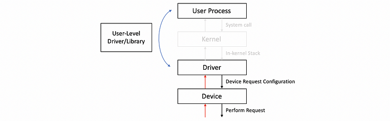
(6) The Definition of Device Drivers
The operating system supports devices via device drivers. Here’s a chart that shows where device drivers sit with respect to the rest of the operating system and the actual hardware they manage.
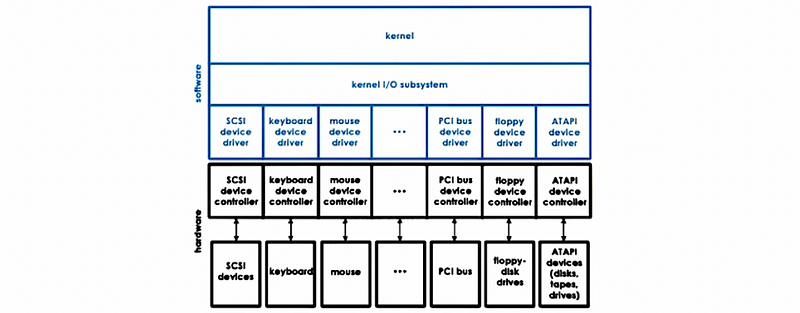
Device drivers are device-specific software components provided by the designers or the manufactures of the hardware, and the OS has to include a device driver for every type of device that is incorporated into the system. What’s more, they are also responsible for all aspects of
- device access
- device management
- device control
The drivers include logic that determines how can requests be passed from the higher-level applications to the device, and there will be standardized interfaced both in terms of the interaction of those devices, as well as in terms of the development and integration of the device drivers. In this way, we will achieve both device independence (i.e. the OS doesn’t have to be specialized) and device diversity (i.e. easy for OS to support different types of devices).
(7) Types of Devices
To deal with device diversity, different devices are grouped into several categories. These include,
- Block Devices: For example, disks. These devices will bring an entire block of data in/out of the device from/to the CPU complex on the other end. The key property is that the blocks can be directly accessed instead of serializing.
- Character Devices: For example, keyboard. The devices should work with a sequence of characters and they will support something like get-a-character, or put-a-character type of interface.
- Network Devices: The network devices are able to deliver more than a character at a time but their granularity is not necessarily to be a fixed block size as block devices. These devices will be more flexible and they will look like a stream of data chunks of potentially different sizes.
(8) Device Abstraction: Special Device Files
Internally, the OS maintains these devices available on the platform by using a file abstraction. In that way, the OS can use any of the other mechanisms that are already part of the OS to manipulate these files. On Unix-like systems, all device files appear in the /dev directory and these files are treaded as a special files system, not the real file system.
For example, we can have a check of all the disk device files by,
$ ls /dev | grep disk
If we have a printer device connected to our Linux system, then this printer has a device file named lp0 (means the first line printer). Then the following command can be used to print Hello, World to this printer device.
$ echo "Hello, World" > /dev/lp0(9) Pseudo Device
Linux also supports what is called pseudo or virtual devices. These devices do not represent actual hardware and they are not critical in I/O management but they are quite useful.
The pseudo-device /dev/null simply accept all the outputs and then discard them, so it is acting as a black hole.
$ echo Hello, World > /dev/null
Another pseudo device /dev/random produces a variable-length string of pseudo-random numbers.
$ cat /dev/random | head -1
(10) Common Device Names
Now let’s see some names of the common devices,
tty: special devices representing terminal stationssda/hda: disks like hard drives, SSDs, CD-ROMs, etc.lp: for printersmem: access to the physical memory- etc.
You can check some of them by,
$ ls /dev | grep sda
$ ls /dev | grep tty
2. CPU and Device Interactions
(1) CPU-to-Device Interactions #1: Memory Mapped I/O
One way the CPU interacts with the devices is by the memory-mapped I/O. When the CPU writes to these physical locations where the device file locates, the integrated memory PCI controller will figure out that this access should be routed to the appropriate device because this memory location is dedicated to interactions with the device. This is called memory-mapped I/O. The portion of the memory that is reserved for these interactions is called by a set of registers called the base address registers (aka. BAR).
(2) CPU-to-Device Interactions #2: I/O Port Model
The other way the CPU can access the devices is via special instructions. For instance, in x86 platforms, there are special in/out instructions that are used for accessing devices. To use these instructions, we have to specify the I/O ports for the target device. This is called the I/O port model.
(3) Device-to-CPU Interactions: Interrupts and Polls
There are two paths for a device to the CPUs. One option is to generate an interrupt to the CPU. The other option is for the CPU to poll the device by reading its status registers in order to determine whether the device needs an interaction.
There are overheads associated with both of these methods and there are some trade-offs between these two options. The interrupt option requires more interrupt handling overheads but we can generate them as soon as we want. For polling, the OS can choose when is the convenient time for us to poll but this will also cause a delay or some CPU overheads.
(4) Programmed I/O (PIO)
The OS can access or request an operation from a device using the programmed I/O (aka. PIO) method. This method requires no additional hardware support and it involves the CPU issuing construction by writing into the corresponding registers like the command registers and the data registers, and then check the status register to decide what to do next.
(5) Programmed I/O: An Example
Let’s see an example about the NIC. For transferring data through the network, we have to follow some steps,
- CPU writes to the command register to request a packet transmission
- CPU copies the packet information into the data register, and this will repeat until the entire package is sent
Let’s say if we have a 1,500 B packet to transmit and the data register can only support 8 bytes at a time. Then the whole operation of a programmed I/O will require one write out for the command, and another 188 (i.e. 1500/8 = 188) accesses to the data register. In total, there will be 189 CPU accesses to the device-specific registers.
(6) Direct Memory Access (DMA)
An alternative to the programmed I/O is to use a direct-memory access (aka. DMA) supported device. The DMA relies on special hardware support called the DMA controller. So although the CPU will still write commands into the command registers on the device, the data movement will be controlled by configuring the DMA controller.
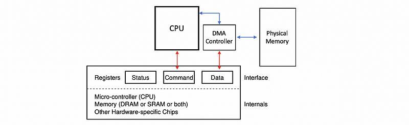
(7) Direct Memory Access (DMA): An Example
Let’s look again at the NIC case and now let’s suppose we have a DMA-based CPU and device interactions. Similarly, there are some steps we have to follow,
- CPU writes to the command register to request a packet transmission
- CPU sends an operation to configure the DMA controller with the information of the in-memory address (i.e. data location) and the size of the packet buffer (i.e. total amount of data)
When this is done, the device can perform the desired operation.
So from the CPU’s perspective, we perform 1 store instruction and 1 DMA configuration in order to transfer a 1,500 B package to the device. This is much better because we only need 2 instructions in total. However, the downside of this method is that the DMA is not a trivial operation and it takes more cycles than a memory store. Therefore, for small transfers, the programmed I/O will still be better than DMA because DMA itself is quite complex.
(8) Typical Device Access Procedure
The typical ways in which a user processes interact with a device are as follows. Let’s say the process needs to perform an operation that requires access from a hardware device and we have to follow the following steps,
- perform a system call: specify the operation and then go to the kernel-mode
- run the in-kernel stack: the in-kernel stack (e.g. TCP/IP stack for the NIC, file system for the disk block) related to the device are going to be executed
- invoke the appropriate driver
- device driver performs the configuration of the request to the device (e.g. write out an appropriate transformation, or issue certain commands for moving the disk heads)
- perform the request: the request will be performed after the device is configured properly
- send back results: any results from the request or any events that are originating on the devices will traverse this chain in a reverse manner (as the red lines)

(9) OS Bypass
However, it is not necessary for us to go to the kernel if we want to get to a device. For some devices, it is possible to configure them to be directly accessed from the user level. This method is called the OS bypass. Since we don’t want the user process to go into the operating system, this driver has to be some user-level driver or the user process should have a user-level device library. Like the device drivers, this UL driver or library should also be provided by the designers or manufacturers.
When bypassing the OS, the OS has to make sure that it still has some kind of coarse-grain control like, for instance, enabling or disabling a device, adding permissions to add more processes to use the device, or etc.
In the regular device stack where the OS is involved, it is the kernel that is aware of the resources that are allocated to each process access to the device. When the OS is bypassed, those types of checks have to be performed by the device itself.
(10) OS Bypass Accessing Block Device
In Linux, the ioctl() command can be used to manipulate the device’s control registers. When the following function is executed, the memory location that’s pointed by the numblocks variable will be filled out with the returned value from the device.
unsigned long numblocks = 0;
ioctl(fd, BLKGETSIZE, &numblocks);
(11) The Definition of Synchronous Access
When an I/O request is made, the user process will require some response from the device. So what will happen once the I/O call is made? The simplest idea is that the current process that calls for this I/O device will simply be blocked. The OS will place this thread on the wait queue and it will eventually become runnable when the response from the request becomes available. This is called synchronous access.
(12) The Definition of Asynchronous Access
The asynchronous access is that the user process is allowed to continue as soon as it issues the I/O call. At some later time, the user process can be allowed to come in and check are the result is ready for retrieving, or the process will be notified by the device or OS after the operation has completed.
(13) Block Device Access Stack
Block devices like disks are typically used for storage and the typical storage-related abstraction used by applications is a file, and now, let’s look closer at how the block devices are used.
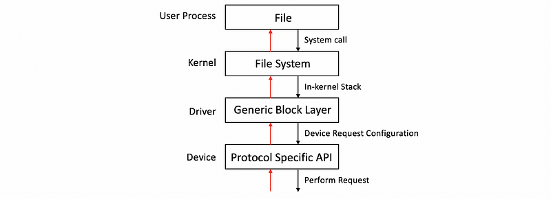
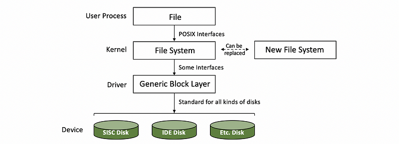
- File: The file is a logical storage unit and it is mapped to some underlying physical storage location. Below this file-based interface used by applications will be the file system.
- File System (FS): The file system will have the information on how to take these reads and writes that are coming from the application and to then determine where exactly is the file, how to access it, what is the particular portion of that file needs to be accessed, what are any permission checks that need to be performed and to ultimately initiate the actual access. The operating systems allow for a file system to be modified or completely replaced with a different file system because it specifies something about the well-defined file system interfaces like the POSIX API. Therefore, the file system can be replaced without modifying the application.
- Hard Drive Devices: If the files are indeed stored on block devices, clearly at the lowest level, the FS will need to interact with these block devices via their device drivers. We can have different types of block devices like SCSI disk or IDE disk that require certain protocol-specific APIs.
- Generic Block Layer: Different types of block devices can have some differences in the errors and so on. In order to mask all of that, the block device stack introduces another layer called the generic block layer. The intent of this layer is to provide a standard for a particular operating system to all types of block devices.
3. Virtual File System Abstractions
(1) A Problem for the Device Access Procedure
We have discussed that we can easily modify or replace the file system with the previous device access procedure we have discussed because the APIs we use are well-defined.
However, there is another problem. In the previous procedure, we can only have one file system and we need to replace the file system if we need to support more platforms. But the process of replacing the file system can be inefficient and the devices will work better if we support more file systems at the same time. What’s more, we may want to communicate with a non-local machine and potentially this machine will have a completely different file system. Therefore, it seems better if we can support multiple file systems at the same time. But how does it possible?
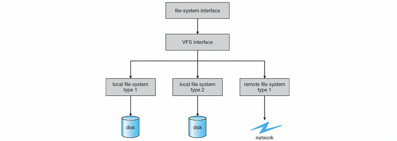
(2) The Definition of Virtual File System (VFS)
To deal with this problem, the Linux operating system uses a virtual file system (aka. VFS) layer, and this layer is responsible for hiding from the applications all details regarding the underlying file system. Therefore, we can now support various types of file systems.
(3) Common File Systems
We have talked a lot about the file systems but we are still not familiar with them. The common file systems are like,
- Linux supported FS: EXT, EXT2, EXT3, EXT4
- Unix supported FS: SysV, Minix
- Microsoft supported FS: MS-DOS, FAT, VFAT, FAT32, exFAT, NFTS
- CD_ROM supported FS: UDF, DVD
- Apple supported FS: HFS, AFFS, ADFS, APFS
- Network FS: NFS, NFSv2, NFSv3, NFSv4
We can check the current file system we are using. On Mac OSX, we can check the FS by,
$ diskutil list
And we may find out that if you have the latest Apple computer, the FS will be APFS.
(4) The Definition of the File
File is one of the key abstractions for VFS. They are the elements on which the VFS operates. The OS represents the files via file descriptors (aka. fd), which are created when the files are opened. There is a number of operations that are supported for files. These operations include,
- open
- read
- write
- sendfile
- lock
- close
- etc.
(5) The Definition of Inode
For each file, the VFS maintains a persistent data structure called an inode (means index node). The inode is a standard data structure in Unix-based systems, and again, it is important because the file doesn’t need to be stored contiguously on the disk and we have to maintain this index for finding the data. The inode contains some important information like,
- list of all data blocks
- permission
- size of the file
- whether lock or not
- etc.
(6) The Definition of Directory
The files are organized in the directory. From the VFS and Unix-based system’s perspective, a directory is really just a file with its contents include information about all the files and their inodes. Therefore, we can find where the data blocks for each file.
(7) The Definition of Dentry
To interpret the directory, Linux maintains a data structure called dentry (means directory entry) and each dentry corresponds to a single path component that’s being traversed as we are trying to reach a particular file. The reason we need to have this dentry is that when we need to find another file that is also stored in the current directory, we don’t have to go through the entire path and reread. The FS will also maintain a cache of all the directory entries that have been visited called dentry cache.
Note that the dentry is in the memory maintained by the OS, so they are not persistent on-disk representation objects.
(8) The Definition of Superblock
There is also a superblock abstraction required by VFS so that it can provide some information about how a particular file system is laid out on some storage device. This is like a map that the FS maintains to figure out how has it organized on disk. Each FS also maintains some additional metadata in the superblock structure that helps during its operation.
(9) EXT2 File System
Now, let’s see an example about the EXT2 file system to have a concrete understanding of the VFS abstractions. EXT2 stands for extended file system version 2. It was a default file system in several versions of Linux until it was replaced by ext3 and then ext4 more recently that are the default versions in more current versions of Linux. It is also available for other operating systems.

- Boot Block: The first block, block 0, is not used by Linux and it often contains the code to boot the computer.
- Block Groups: The rest of the storage is divided into block groups and the sizes of these groups have nothing to do with the physics of the disks
- Superblock: The first block in a block group is the superblock and this contains information about the overall block group. It will have information about the # of inodes, about the # of disk blocks in this block, and it will also have information about the start of the free blocks.
- Group Descriptor: describes the overall state of the block group. It has bitmaps, the # of free nodes, the total #of directories in the system. This information is useful when files are being allocated because ext2 tries to balance the overall allocation of directories and files across the different block groups.
- Bitmaps: used to quickly find a free block or a free inode, so for every single inode in this particular group and every single data block, the bitmap will be able to tell the upper layer allocators whether that inode component or that data block is free
- Inodes: number from 1 up to some maximum number. And every one of the inodes is in ext2 a 128-byte long data structure that describes exactly 1 file. It will have information like the owner of the file, some accounting information that system calls like stat would return, and also some information on how to locate the actual data blocks.
4. Understanding Inode
(1) Get the Inode of a File
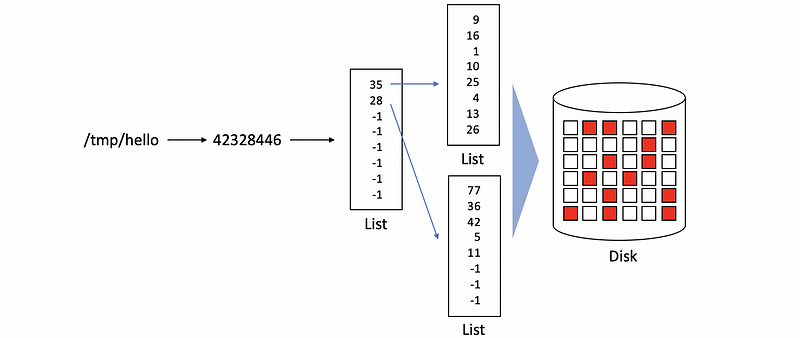
We have said that in the Linux or Unix-like system, the files can only be found through the inode of this file. So the file names are actually something for human reads, and the machine can not find the files directly by the file names. So every time when we try to access a file, what we will actually do is to first find the inode of this file.
To get an inode of a file, let’s first create a new file in the /tmp directory and then we will manually get its inode index by stat command. We can create a new file named hello by,
$ echo "Hello, World" > /tmp/helloThen, we can use the stat command to get its inode index,
$ stat -f %i /tmp/hello
Suppose the output we have is,
42328446
And we will use this inode index for our following discussion. Remember now, we have a mapping rule of,

(2) Find the File Data By Inode
So now we have the inode of this file, but where can we find the data of this file? Recall that the blocks are some fixed-size storage and it can be much smaller than our file. So in order to keep the data of our files, we may use several blocks for storing a single file.
What’s more, all these blocks are not necessarily consecutive and they can distribute discretely in the hard disk. In order to be able to find all the related blocks of a file, the inode itself contains a list of all the blocks that correspond to the actual file.

(3) Inode Metadata
The inode also has some metadata information, and this is useful to keep track of whether or not certain file accesses are legal or to correctly update the status of the file (if it is locked or not locked). We can use the stat command to show all the inode metadata,
$ stat /tmp/hello
And the printed result can be interpreted as,
- Device ID
- Inode number
- Permissions (mode)
- Hard link count (usually 1)
- File userid (owner)
- File grouped
- Device ID
- Size in bytes
- Last access time
- Last (contents) modification time
- Last permissions change time
- Create time
- The ideal block size for file
- 512-byte-size blocks allocated for the file
- Flags set on file
(4) Inode Performance
For the inode we have discussed, the benefit of this list approach is that it is easy to perform sequential or random access to the file because all the blocks that correspond to the file can be easily found from the list elements. However, there is a problem with the file size. Because we have a list with a limited number of elements, so the total size of blocks is limited. Therefore, we will reach a barrier if we keep enlarging the file size.
(5) Inode with Indirect Pointers
One way for this problem is to improve the inode with indirect pointers. So the new pointer will not point directly to the blocks, instead, it will point to some new lists. And if we have a single indirect pointer, the pointers in the new list will directly point to the disk blocks.
Also, we can have double indirect pointers or triple indirect pointers if we have an even larger file.
The benefit of this approach is that now we can maintain a large file size even with a small inode size. However, the downside is that the file access will be slow down because we have to traverse more lists in order to get direct pointers to the disk blocks.
(6) Techniques for Disk Access Optimizations
File systems use several techniques to try to minimize access to the disk and to improve the file access overheads. These include,
- Caching/Buffering: reducing the disk accesses
- I/O Scheduling: reducing disk head movement
- Prefetching: benefit from locality
- Journaling/Logging: reduce random access (EXT3, EXT4)